 ChipBuddy
← Home
ChipBuddy
← Home
Special Checks: Latches, Gating, CDC
Chapter 13 — Special Timing Checks: Latches, Clock Gating,
Generated Clocks & CDC
So far we mostly studied one simple case. A flip-flop launches data on one clock edge. The next flipflop captures it on a later edge. We close a setup window and a hold window. Real chips are messier. They use latches that stay open for half a cycle. They use clock gates that turn the clock on and off. They use clocks that are divided or multiplied from a main clock. They use resets that must release cleanly. They pass signals between unrelated clocks. Each case breaks the simple two-flop picture. Each one needs its own special check (a timing test built for that situation). This chapter covers those checks, the commands that enable them, and how to reason about them.
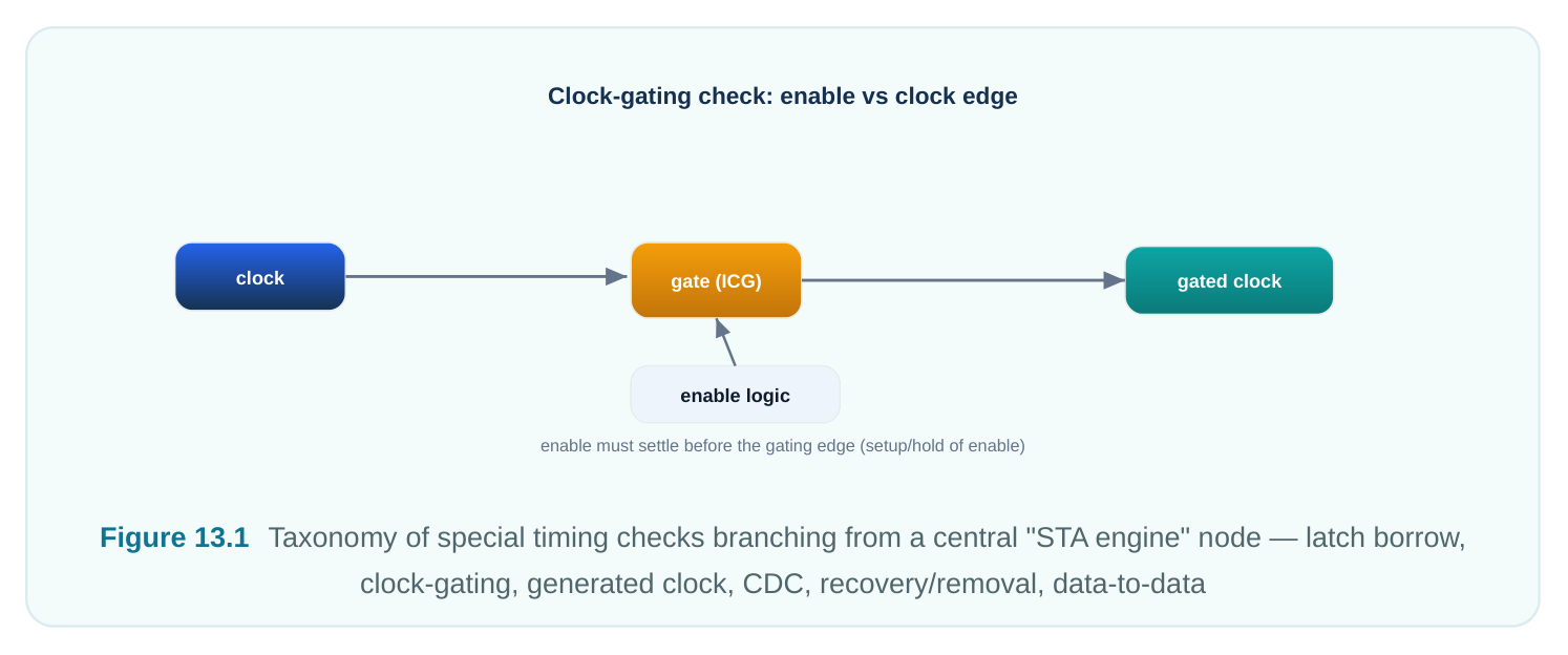
13.1 Why "special" checks exist
A normal setup/hold check assumes two things. First, the capture flop samples on one sharp clock edge. Second, the launch and capture clocks are related (they share a period and a fixed phase). When either assumption breaks, the tool needs more info. Or it needs a different equation. The table below previews the checks in this chapter.
| Check | What it verifies | Primary constraint / mechanism |
|---|---|---|
| Time borrowing | Slow logic into a transparent latch can | set_max_time_borrow , library latch |
| (latch) | use part of the next phase | timing |
| Clock-gating | Enable settles before the clock edge setup/hold | set_clock_gating_check that the gate must pass/block |
| Generated-clock | Divided/multiplied clock edges line up alignment | create_generated_clock with the master correctly |
| Async crossing | Crossing is structurally safe; STA does | set_false_path / set_max_delay - |
| (CDC) | not time the metastable arc | datapath_only |
| Half-cycle path | Capture edge is half a period from | derived automatically from clock waveform |
launch
| Recovery / | Async set/reset is released a safe | library recovery/removal arcs |
|---|---|---|
| removal | distance from the active clock edge | |
| Data-to-data | Two data signals hold a required | set_data_check |
separation (no clock)
13.2 Latch-based timing and time borrowing
A flip-flop captures on an edge. A level-sensitive latch is different. It is transparent (data flows straight through) while its enable is at the active level. It is opaque (data is frozen) otherwise. During the open
window, the input passes right to the output. This open window is the basis of time borrowing (also called cycle stealing or slack borrowing). Picture a path. It launches from a latch. It runs through slow logic. It arrives at a second latch. That second latch opens at the midpoint of the cycle. The capture latch stays open for a while after it opens. So the data does not need to arrive before the latch opens. It only needs to arrive before the latch closes. In effect, the late stage borrows time from the start of the next phase. The next stage pays that time back. It now has less time to work with. Think of it like a relay race. A slow runner can cross the line late. But the next runner then starts late too.
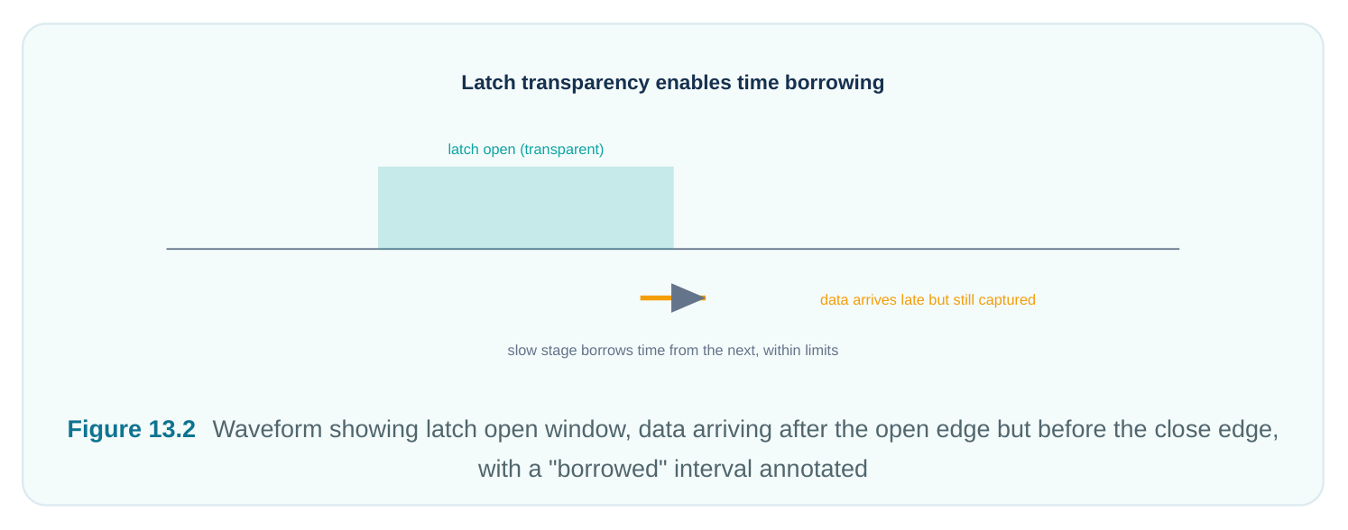
STA tracks borrowing with a few numbers.
| Quantity | Meaning |
|---|---|
| Borrow limit | Maximum time a stage may steal, bounded by the transparency window width minus |
setup
| Actual borrow | How much this particular path used |
|---|---|
| Borrow | Remaining headroom in the window |
available
Library limit Cap imposed by the latch's own timing (and any set_max_time_borrow ) closing edge. Once the latch goes opaque, the value is locked. Say a path tries to borrow more than the limit. The tool clamps the borrow at the maximum. It then reports a setup violation for the leftover amount. Designers cap borrowing on purpose. This stops one greedy stage from starving every stage after it.
# illustrative — generic, not tool-specific
# Limit how much any latch in this group may borrow
set_max_time_borrow 0.300 [get_pins core/lat_*/G]
There is a subtle trap with latches. Slack flows across latch boundaries. A path that closes timing only by borrowing pushes its problem forward. So engineers read borrow reports as a chain. They do not read them as separate endpoints.
13.3 Clock-gating checks
Clock gating saves power. It stops the clock to logic that is idle. But there is a clear danger. Say the enable changes while the clock is high (for an AND-type gate). It can chop the clock pulse. This makes a glitch or a runt pulse (a short, broken pulse). That can corrupt every flop downstream. A clock- gating check times the enable against the clock. It makes sure the enable only changes during the inactive level of the clock. Toggling there is harmless. Take an AND gate that passes the clock when enable is high. The enable must stay steady while the clock is high. So it may only change while the clock is low. The check enforces two things:
- a setup rule: the enable must settle before the clock's rising edge, and
- a hold rule: the enable must stay steady until after the falling edge (or until the gate is safely closed). For an OR-type gate the polarity flips. Tools usually add the gating check by themselves on known clock-gating cells. But you can declare it yourself:
# illustrative — generic, not tool-specific# Force a high (rising-edge) gating check on a custom AND gateset_clock_gating_check -high -setup 0.090 -hold 0.045 \[get_pins cg_inst/and_gate/A]A sample gating report makes it concrete:# illustrative — generic, not tool-specificClock Gating Check (setup) : cg_inst/and_gaterelated clock : clk (rise @ 6.000)enable arrival (max) : 5.840required (edge-setup): 5.910 (6.000 - 0.090)slack : +0.070 METHere is the mental model. Treat the enable like data. Treat the gating cell like a capture flop. Its "edge" is the clock edge that must not be disturbed. The check makes sure the gate opens and closes only on clean clock levels.
13.4 Generated, divided, and multiplied clocks
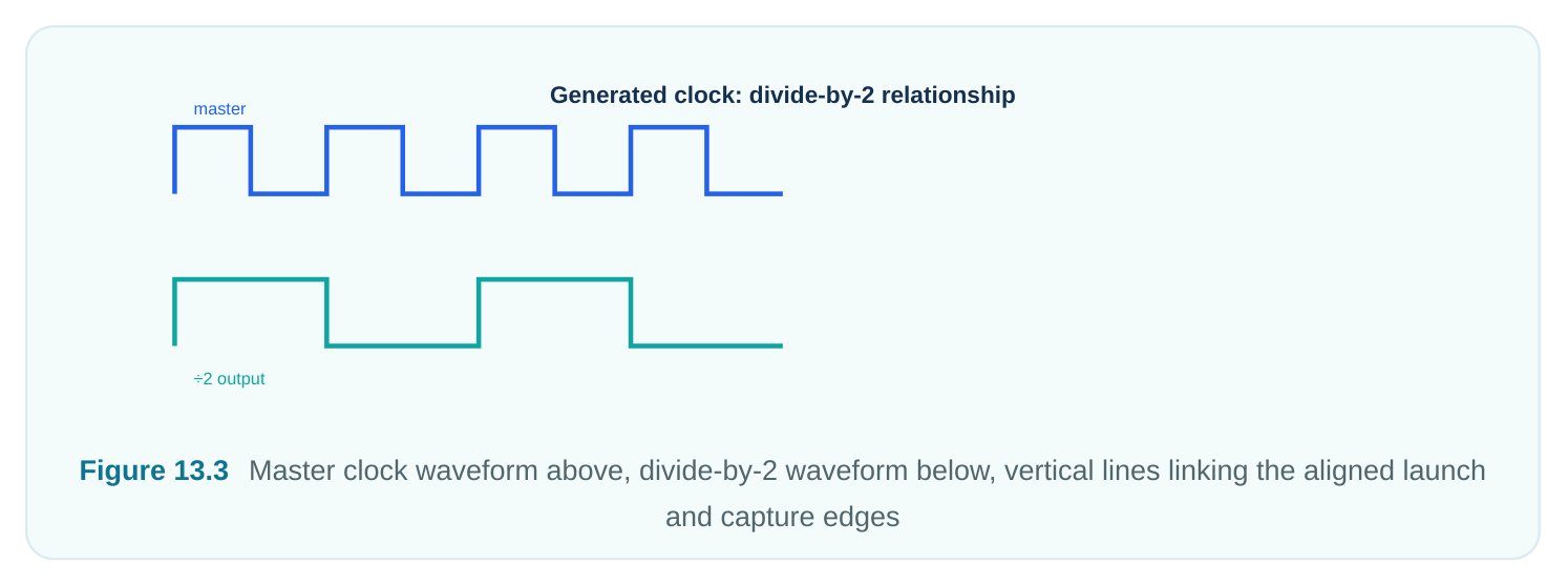
Most chips build secondary clocks from a main clock. A divide-by-2 for a slow part. A PLL-multiplied core clock (PLL is a circuit that makes a faster clock). A gated or inverted version for one block. The timing tool cannot guess this link. It must be told. The link decides which launch edge pairs with which capture edge.
A create_generated_clock declares the new clock. It names the source pin. It gives the math relationship to the main clock. The tool can then build the right waveform and line up edges:
# standard (SDC)
# Divide-by-2 clock at the Q output of a divider flop
create_generated_clock -name clk_div2 \
-source [get_pins pll/CLKOUT] -divide_by 2 \
[get_pins div_reg/Q]
# A multiplied (PLL output) clock relative to the reference
create_generated_clock -name clk_core \
-source [get_ports ref_clk] -multiply_by 6 \
[get_pins pll/CLKOUT]
Why does this matter? Say you forget to declare the divided clock. The tool may treat the divider output as plain data. It may time it against the main clock with a wrong edge relationship. Or it may leave the whole downstream domain unconstrained. Either way your sign-off is wrong. Declaring it lets the tool find the true launch/capture edge gap. For a divide-by-2 path that gap can be a full main-clock period. The rule is simple. Every clock a flop sees must be defined. Any clock that is not a primary input should be a generated clock tied to its real source. That keeps edge phases correct.
13.5 Multi-clock and cross-clock-domain (asynchronous) paths
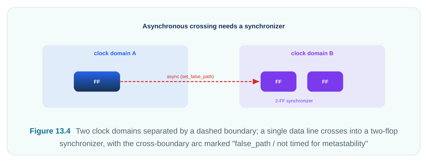
Sometimes launch and capture clocks are synchronous. They come from a common root. They have a known period ratio. Then STA finds the worst-case edge pair. It times the path normally, even across different speeds. Trouble starts with asynchronous clocks. These are two separate oscillators, or clocks with no fixed phase. Their edges drift past each other all the time. For a truly async crossing, the launch and capture edges can land any distance apart. There is no real setup or hold rule to enforce. The window the data must hit moves every cycle. Forcing the tool to time it gives junk slack that always fails. The right answer is a synchronizer. This is usually two or more flops in a row in the destination domain. It gives any metastable state at the first flop time to settle before the value is used. (Metastable means a flop is stuck between 0 and 1 for a moment.)
This is key. STA does not time the metastable arc. Metastability is a probability thing. We measure it by Mean Time Between Failures (MTBF). MTBF depends on technology constants, clock frequency, and data rate. STA checks the synchronizer structurally. It confirms the two flops exist. It confirms they are next to each other. It confirms the path between them stays inside the destination domain and is timed normally. The cross-domain arc into the first flop is left out of setup/hold checking. The MTBF margin is a separate analysis. It uses the library's metastability data, not the slack equation. Here is how we constrain these crossings.
| Crossing type | Recommended handling | Constraint |
|---|---|---|
| Truly asynchronous, properly synchronized | Exclude the arc from setup/hold | set_false_path between domains |
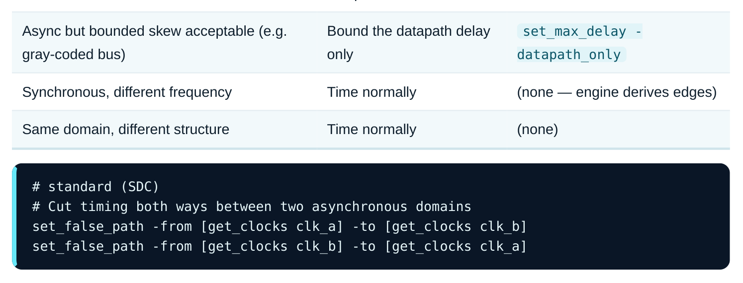
A false path tells the tool "do not check setup/hold here." That is correct only when a synchronizer (or a handshake or FIFO) is really there. Using it just to silence violations is a classic, dangerous mistake. Sometimes you do care how much the data can skew. Take an async bus with many bits. They must all arrive within one destination period of each other. Otherwise you sample a torn value. Here you do not cut the path. You bound only the logic delay. You ignore the (meaningless) clock relationship:
# standard (SDC)
# Bound only the datapath portion across the crossing
set_max_delay 2.000 -datapath_only \
-from [get_pins src_dom/data_reg*/Q] \
-to   [get_pins dst_dom/cap_reg*/D]
The -datapath_only flag is what makes this safe. It limits the logic delay. It does not impose a fake clock-edge relationship. Without it the constraint could never be met.
13.6 Half-cycle paths and unusual capture relationships
Not every path captures one full period after it launches. Say a path launches on a rising edge. It then captures on the next falling edge of the same clock. That is a half-cycle path. It has only half a period to finish. These show up between a rising-edge flop and a falling-edge flop. They also show up between phases in a latch design. The tool finds the half-cycle relationship by itself from the clock waveform. You do not declare it. But you must know it is there. A half-cycle setup path is tighter than you expect (less time). Its matching half-cycle hold check is looser. Multicycle exceptions can also make odd capture relationships. They stretch a path across several cycles. But those are deliberate set_multicycle_path declarations. They are different from the auto-derived half-cycle case. The lesson is simple. Always read the launch and capture edge times in the path report. Do not assume a full period.
13.7 Recovery and removal (async set/reset)
Some flops have asynchronous set or reset inputs. These need their own checks. The checks apply at the moment the async signal is released. Say the reset deasserts too close to an active clock edge. The flop may go metastable on its first real clock. That is exactly the failure async resets were meant to avoid.
- Recovery is a setup-like check. The async control must deassert at least recovery time before the active clock edge.
- Removal is a hold-like check. The async control must stay asserted until at least removal time after the active clock edge. These arcs come from the cell library. You do not normally constrain them. But you do report and close them. The usual fix is a reset synchronizer. It lines up reset deassertion with the local clock. A sample report:
# illustrative — generic, not tool-specific
Recovery Check : u_block/state_reg
reset deassert (max arrival) : 4.880
clock active edge            : 5.000
recovery requirement         : 0.070
required time                : 4.930   (5.000 - 0.070)
slack                        : +0.050  MET
13.8 Data-to-data checks
Some interfaces need two data signals to keep a fixed gap. No clock is involved. Take a custom memory. The address must be steady for a set time before the write strobe pulses. A data-to-data check ( set_data_check ) sets a setup/hold-style rule between two ordinary pins. One pin is the "related" (reference) signal. The other is "constrained":
# standard (SDC)
# Require addr stable 0.25 ns before the write strobe, and held 0.15 ns after
set_data_check -setup 0.250 -from [get_pins mem/addr_valid] \
-to [get_pins mem/wr_strobe]
set_data_check -hold  0.150 -from [get_pins mem/addr_valid] \
-to [get_pins mem/wr_strobe]
This is the right tool when a relationship looks like setup/hold. But the two signals are not clock and data in the usual sense.
Interview Q&A
next stage still meets timing after the 250 ps is paid back. Borrowing is not free. It shifts the start of the next stage later. That eats into the next stage's budget. Always trace the borrow chain across latch boundaries. A path that borrows the maximum often pushes a violation onto the next stage. The real fix may be balancing logic across phases, not relying on transparency.
fixed launch-to-capture edge relationship. The two clocks drift. So the sampling window moves every cycle. Worst-case alignment is basically zero margin. The check would always fail. The crossing is made safe by a synchronizer. It gives metastability time to settle. That safety is a probabilistic MTBF property, not a slack number. STA's job is to confirm the synchronizer exists and to exclude the unbounded arc. It uses a false path or a -datapath_only max delay.
clock. Say the enable to an AND-type gate toggles while the clock is high. It can chop the clock pulse. Then every flop fed by that clock can mis-capture. The check forces the enable to change only while the clock is at its inactive level. It needs a setup margin before the active edge and a hold margin after. So the gate opens and closes on clean clock levels.
The tool has no idea the divider output is a clock. It may treat it as data and time it against the main clock with the wrong edge relationship. Or it may leave the whole downstream domain unconstrained and silently "clean." Either way your sign-off is invalid. Declaring the generated clock with its source and divide ratio fixes this. The tool builds the true waveform and lines up launch/capture edges. For a divide-by-2 crossing that can mean a full main-clock period of separation the default would never compute.
Key Takeaways
- Latches enable time borrowing: transparency lets a slow stage steal from the next phase. But the borrow is capped at the window width minus setup, and it must be paid back. Read borrow as a chain across latch boundaries.
- Clock-gating checks keep the enable changing only on the clock's inactive level. This prevents glitched or runt clock pulses. Model them as setup/hold of enable versus the protected clock edge.
- Generated clocks must be declared with their true source and divide/multiply ratio. This lets the tool line up launch and capture edges. An undeclared derived clock gives invalid or missing checks.
- Asynchronous crossings cannot be timed by slack. Use synchronizers. Exclude the arc with
set_false_path, or bound logic withset_max_delay -datapath_only. Metastability is an MTBF analysis, verified structurally, not by STA timing. - Half-cycle paths are derived automatically and are tighter than full-cycle paths. Always check the actual launch/capture edges in the report.
- Recovery/removal guard async set/reset release around the active edge. Data-to-data checks impose setup/hold-style separation between two non-clock signals.
Comments
Leave a Reply