 ChipBuddy
← Home
ChipBuddy
← Home
Crosstalk & Signal Integrity in STA
Chapter 12 — Crosstalk & Signal Integrity in STA
In older chips, wires were far apart. Timing depended only on gates and single nets. In modern chips, wires are packed tightly. They run side by side across many metal layers. The capacitance (ability to store charge) between neighbors grows large. It can match or beat each wire's capacitance to ground. When this happens, a neighbor's behavior changes your timing. This is the world of signal integrity (SI) (how clean and correct a signal stays). Crosstalk (one wire disturbing another) is its main effect in static timing analysis. This chapter explains why SI happens. It shows how SI changes both delay and logic. It shows how STA limits the problem using switching windows. It shows how to read the reports and act.
Why Signal Integrity Matters at Nanometer Nodes
Two parallel wires act like a tiny capacitor. Their facing side walls store charge between them. Call the wire we study the victim. Call the noisy neighbor the aggressor. When the aggressor changes voltage, charge flows onto the victim. The current is $i = C_c \cdot dV/dt$. Here $C_c$ is the coupling capacitance. That charge must go somewhere. It either helps the victim switch, fights it, or makes a bump on a quiet victim. Three trends make this unavoidable. First, wires got thin and tall. So side wall coupling dominates total net capacitance. Second, spacing shrank. So $C_c$ grew. Third, edges got faster. So $dV/dt$ rose, and the same capacitor injects more current. Ignoring coupling here is not safe. It is simply wrong. It misleads in both the optimistic and pessimistic direction.
Crosstalk: aggressor couples onto victim aggressor victim coupling capacitance pushes/pulls the victim edge
Figure 12.1 Two parallel routed wires (aggressor above, victim below) with coupling capacitor Cc between them
and Cg to ground on each; arrow showing injected current i = Cc·dV/dt Here is the key shift in thinking. A victim's delay is not a fixed number. It depends on what its aggressors do at the same moment. So STA must reason about timing overlap. It cannot just use the worst isolated delay.
Crosstalk Delay: The Delta Delay Effect
The most common SI timing effect is a change in path delay. We call it delta delay ($\Delta d$). Its sign depends on the switching directions of the two nets.
- Same direction (both rise, or both fall): the aggressor helps the victim move. Both plates of the coupling cap swing together. So it stores little charge. The victim sees a smaller load. The victim switches faster, so delay drops. This is the risky case for hold checks and min-delay paths. A path you thought was slow may arrive too early.
- Opposite direction (one rises while the other falls): the aggressor pulls the cap the other way. The victim's driver must supply extra charge to win. The coupling looks bigger. This is the Miller effect, which can more than double $C_c$. The victim switches slower, so delay grows. This is the risky case for setup checks and max-delay paths. Aggressor vs. Victim Which check it Effective coupling Delay effect victim edge endangers Same direction Reduced (≈0 to 1× Cc) Faster Delta delay negative Hold / min-delay (speed-up) Opposite Amplified (≈1× to 2×+ Slower Delta delay positive Setup / max-delay direction Cc, Miller) (slow-down) Quiet (steady) Physical Cc as static None on Glitch risk instead Noise / functional load edge One victim often has many aggressors. SI-aware STA adds up their effects. But it counts only those that can switch at the same time as the victim. The result is a delay adjustment per arc. It sits on top of the normal delay.
Crosstalk Noise: The Glitch on a Quiet Victim
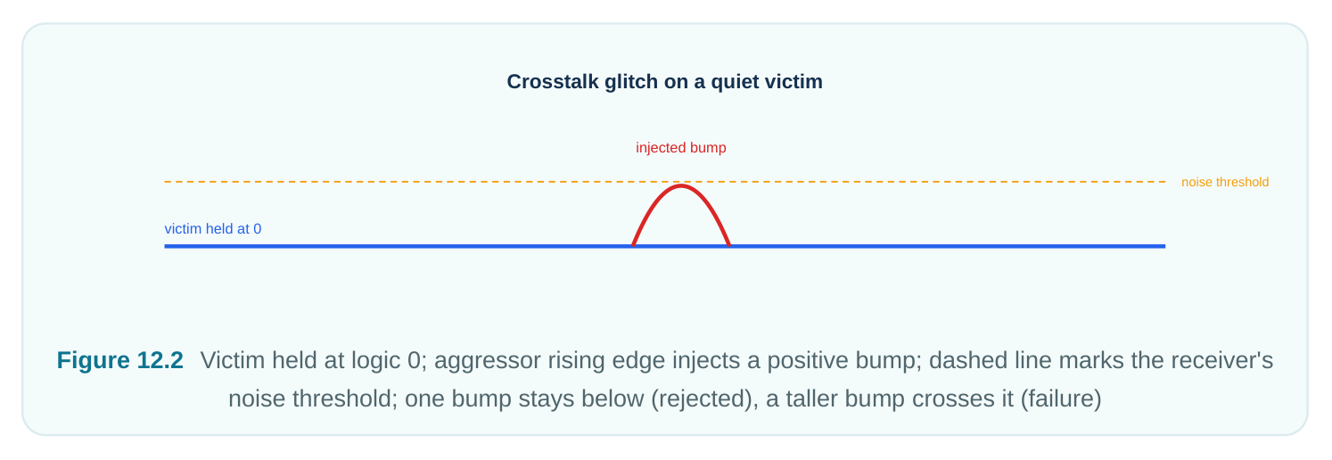
Delta delay assumes the victim is switching. But what if the victim sits still? Say it holds a steady 0 while an aggressor swings hard. The injected charge makes a short voltage bump. We call it a glitch or crosstalk noise. Two questions then matter.
- 1. How big is the glitch? A gate flips when its input crosses a switching threshold (the trip point). If
the bump crosses that level, the gate may read a false flip. The bump height grows with the coupling ratio and a faster aggressor edge. A strong victim driver pulls the node back toward its rail, so it shrinks the bump.
- 2. Where does it land? A glitch on a data net near the clock edge can be stored as wrong data. A
glitch on a clock, reset, or set net is worse. It can fire a false capture or scramble state. A glitch on a logic path may travel through later gates. Sometimes it fades. Sometimes a chain of sensitive gates makes it worse. So STA separates two outcomes. Noise rejection means the receiver ignores the bump. Noise propagation means the bump survives and travels. Noise analysis gives a noise slack. That is the margin between the real glitch and the level the receiver can safely ignore. Negative noise slack is a functional risk. It is not just a speed risk.
Switching Windows: When SI Actually Applies
One idea keeps SI analysis from being far too harsh. It is the switching window (also called a timing window). An aggressor can hurt a victim's edge only if the aggressor can switch in the same time span. Each net has an arrival window. That is the earliest-to-latest span when its edge can happen. STA gets it from the timing graph. Say the two windows do not overlap. Then the aggressor cannot inject charge while the victim switches. So it adds no delta delay. It may still add static load. Say the windows do overlap. Then the aggressor counts. Its worst-case effect is included. This makes a chicken-and-egg loop. Windows depend on delays. SI delays depend on which aggressors overlap. Overlap depends on windows. SI-aware STA breaks the loop with iterative convergence (repeating until answers settle):
- 1. Find delays with no crosstalk to get starting windows.
- 2. Find aggressor and victim overlaps from those windows.
- 3. Find delta delays for the overlapping aggressors.
- 4. Redo path delays and windows with the new delta delays.
- 5. Repeat until windows and delays barely change.
| SI concept | What it captures | Why it matters |
|---|---|---|
| Switching window | Earliest–latest transition time of a net | Gates whether an aggressor can |
couple
Window overlap Coincidence of aggressor and victim Decides if delta delay is counted
| Iterative | Re-solving delays ↔ windows | Avoids both over- and under- |
|---|---|---|
| convergence | pessimism | |
| Delta delay | Per-arc delay adjustment from coupling | Enters setup/hold path delays |
| Noise slack | Margin vs. receiver glitch tolerance | Functional (logic) safety, not speed |
Most flows let you trade runtime for accuracy. A few passes are usually enough. You can also limit work to overlapping windows only. Or you can use a quick "all aggressors always overlap" mode for a very harsh bound.
The Factors That Drive Crosstalk Severity
A few factors decide if a coupled pair becomes a real fault.
- Coupling capacitance ratio — $C_c / (C_c + C_g)$. This is the share of total cap that is coupling, not grounded. A bigger share lets the aggressor inject more charge. This is the strongest single knob.
- Relative drive strength. A weak victim driver has high output resistance. It cannot hold its node against injected charge. So it gets bigger glitches and bigger delta delays. A strong aggressor pushes more current.
- Slew (how fast an edge moves). A faster aggressor edge means a larger $dV/dt$. So it injects more current. A slow victim edge sits near the threshold longer. That widens the time when coupling can hurt.
- Victim quietness. A victim that switches hard somewhat defends itself. A quiet victim is most at risk. That is true for nets held by a weak keeper or left nearly floating.
Mitigations as STA Sees Them
SI problems are fixed in the layout and circuit. STA's job is to confirm the fix worked. Here are common fixes and what STA sees.
| Mitigation | Physical action | Effect STA observes |
|---|---|---|
| Increase spacing | Move victim/aggressor wires | Lower Cc → smaller delta delay and glitch |
apart
| Shielding | Route grounded/power lines | Replaces signal coupling with stable-rail cap; |
|---|---|---|
| beside the net | near-zero delta delay | |
| Upsize victim driver | Stronger cell driving the victim | Faster recovery, smaller glitch, less delta |
delay
Reduce aggressor slew / Tame the offending driver Lower dV/dt → less injected current
Net ordering / layer Reroute on a less hostile track Removes the overlapping aggressor entirely
| Buffer insertion / shorter | Break up long coupled | Reduces total coupled length, hence Cc |
|---|---|---|
| parallel run | segments |
After any fix, run SI-aware STA again. It should show less delta delay on the affected arcs. It should show better noise slack at the affected receivers.
A Worked Delta-Delay Example
Take a setup path through a victim net's stage. Its nominal delay, with no coupling, is 240 ps. The victim has one strong aggressor. That aggressor's switching window overlaps the victim's edge. Let the coupling capacitance be $C_c = 8\ \text{fF}$. Let the victim driver's effective resistance be $R = 4\ \text{k}\Omega$. For an opposite-direction slow-down, the Miller multiplier roughly doubles the coupling. So the driver charges an extra $2 \times C_c = 16\ \text{fF}$. A first-order delay penalty is about $0.69 \cdot R \cdot C_{\text{eff}}$: $$\Delta d \approx 0.69 \times 4\,\text{k}\Omega \times 16\,\text{fF} \approx 44\ \text{ps (slow-down)}$ $ So the max-delay (setup) view of this stage becomes $240 + 44 = 284\ \text{ps}$. Say the path had +35 ps of setup slack before. It now shows $35 - 44 = -9\ \text{ps}$. That is a violation made purely by crosstalk. Now look at the same pair in the min-delay (hold) view. Here the aggressor switches in the same direction. The effective coupling shrinks toward zero. So we get a small speed-up. Say the same math with an effective $\sim3\ \text{fF}$: $$\Delta d \approx 0.69 \times 4\,\text{k}\Omega \times 3\,\text{fF} \approx 8\ \text{ps (speed-up)}$$ So the hold view of the stage becomes $240 - 8 = 232\ \text{ps}$. That eats 8 ps of hold margin. Notice the gap. The same net hurts setup by 44 ps in one case. It hurts hold by 8 ps in another. SIaware STA must use the worst relevant direction for each check on its own. These numbers are simple
first-order estimates. Real tools use detailed driver and receiver models. But the direction logic is exactly this.
Reading and Enabling SI in STA
The exact commands to turn on SI and pull reports differ by tool. The snippets below are conceptual.
# illustrative — generic, not tool-specific
# Enable crosstalk/SI-aware delay and noise analysis
set_si_analysis -delta_delay true -noise true
set_si_options  -window_overlap true -max_iterations 4
Switching windows and aggressor lists come from constraints you already wrote in standard SDC. The clocks and exceptions that shape windows are real SDC:
# standard (SDC)
create_clock -name CLK -period 1.0 [get_ports clk]
set_input_delay  0.20 -clock CLK [get_ports din]
set_output_delay 0.20 -clock CLK [get_ports dout]
set_false_path -from [get_ports test_mode]   ;# narrows real switching windows
Pulling SI-specific reports also uses tool-specific commands. These give delta delay per arc and noise slack per receiver:
# illustrative — generic, not tool-specific
# Worst delta-delay contributors on a victim net
report_delta_delay -net victim_net -max_paths 10
# Noise (glitch) analysis and slack at receivers
report_noise -slack_lesser_than 0.0 -nworst 20
# Identify aggressors and their overlapping windows for a victim
report_crosstalk -victim victim_net -aggressors -windows
When you read these reports, focus on three things. First, the sign and size of delta delay on critical arcs, split by setup and hold. Second, the noise slack at sensitive receivers. Watch clocks, resets, and flop data inputs. Third, the list of top aggressors. That list tells place-and-route which neighbor to spread, shield, or reroute.
Interview Q&A
instead of slowing it down? Delay depends on how much charge the victim's driver must move across the coupling cap. When both plates swing the same way at once, the voltage across the cap barely changes. So it stores little charge and acts as a small load. The driver finishes faster. In the
opposite case, the far plate moves against the victim. The driver must supply charge for nearly double the swing, due to the Miller effect, so the edge slows.
window is the earliest-to-latest time when a net can switch. STA takes it from the timing graph. An aggressor adds delta delay only if its window overlaps the victim's window. Without windows, you would assume every neighbor switches at the worst instant. That gives wildly harsh delays. Windows let STA count only aggressors that truly coincide. That is why delays and windows must be solved together by iteration.
dangerous? Delta delay shifts the timing of a victim that is switching. It costs or saves picoseconds on a path. Noise is a glitch on a victim that should stay quiet. It is a functional hazard. If the bump crosses the receiver's threshold, it can be stored as wrong data. On a clock, set, or reset, it can fire false behavior. No clock-period margin protects against that. Noise is reported as noise slack against a glitch-tolerance level. It is separate from setup and hold slack.
steps? Run a delta-delay report on the victim. Confirm crosstalk is the cause and measure the penalty. Then list aggressors with overlapping windows to find the worst one. Check the coupling ratio $C_c/(C_c+C_g)$, the aggressor's slew, and the victim driver's strength. The fixes follow the cause. Spread or shield the net to cut $C_c$. Upsize the victim driver. Tame the aggressor's slew. Or reroute to remove the overlap. Also check that the aggressor's window is real. A missing false path or a wrong constraint can make a quiet net look like an aggressor and inflate the violation.
Key Takeaways
- At nanometer nodes, side wall coupling makes a victim's delay a function of its neighbors, not a fixed value; ignoring it is wrong in both directions.
- Delta delay is signed: same-direction aggressors speed the victim (a hold/min-delay risk), opposite-direction aggressors slow it via the Miller effect (a setup/max-delay risk).
- Crosstalk noise is a glitch on a quiet victim — a functional hazard measured by noise slack, distinct from timing slack and especially dangerous on clock/reset/set nets.
- Switching windows gate which aggressors count; delays and windows are solved by iterative convergence to avoid both over- and under-pessimism.
- Severity is driven by the coupling ratio, relative drive strength, slew, and victim quietness — and is mitigated by spacing, shielding, driver sizing, slew control, and rerouting.
- SI-aware STA reports delta delay per arc and noise slack per receiver, plus the dominant aggressor list that tells physical design exactly what to fix.
Comments
Leave a Reply