 ChipBuddy
← Home
ChipBuddy
← Home
Clock Waveforms & Duty Cycle
Clock Waveforms and Duty Cycle
A clock is the heartbeat of a digital chip. In timing, a clock is described by its waveform. A waveform is the shape of the clock signal over one period. The period is the time for one full cycle, measured in nanoseconds (ns). Inside SDC (the timing constraint format), we draw this waveform with two numbers: when the clock rises and when it falls. Most people imagine a clock as a perfect square wave. It is high for half the time and low for the other half. That balanced shape is a 50% duty cycle. Duty cycle is the fraction of the period that the clock stays high. But real clocks are not always balanced. Some stay high longer than they stay low. Some do the opposite. When that happens, the duty cycle is no longer 50%, and we must say so in the constraint. This chapter explains how to define waveforms, how to set non-50% duty cycles, and why the exact placement of the rising and falling edges changes the timing the tool checks. Edge placement matters most for half-cycle paths. A half-cycle path is a path that launches data on one edge and captures it on the opposite edge. If you place an edge wrong, the tool measures the wrong window, and your chip can fail.
How a Waveform Is Defined
The waveform of a clock has two edges per period. One is the rising edge, where the signal goes from low to high. The other is the falling edge, where the signal goes from high to low. In SDC, we list these
edge times inside a -waveform option. The first number is the first rising edge. The second number is the first falling edge. Say the period is 4.36 ns. A balanced clock rises at time 0 and falls at the halfway point, 2.18 ns. So the waveform list is {0 2.18} . The tool then repeats this pattern every 4.36 ns forever. The next rising edge is at 4.36 ns, the next falling edge at 6.54 ns, and so on. If you do not give a -waveform at all, the tool assumes a default. The default is a 50% duty cycle that rises at time 0. So create_clock -period 4.36 alone means the same as a waveform of {0 2.18} . You only need to write the waveform when you want something other than the balanced default.
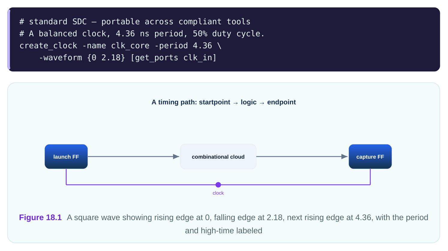
The high time is the gap from the rising edge to the falling edge. The low time is the gap from the falling edge back to the next rising edge. For the balanced clock above, both are 2.18 ns. The duty cycle is the high time divided by the period: 2.18 / 4.36 = 50%.
Defining a Non-50% Duty Cycle
To make a clock that is high longer than it is low, push the falling edge later. Suppose the period is 5.12 ns and you want a 60% duty cycle. The high time must be 60% of 5.12 ns, which is 3.072 ns. So the clock rises at 0 and falls at 3.072 ns. The waveform list becomes {0 3.072} . To make a clock that is high less than it is low, pull the falling edge earlier. For a 35% duty cycle on the same 5.12 ns period, the high time is 0.35 × 5.12 = 1.792 ns. The waveform is {0 1.792} . The clock is now low for 3.328 ns of every cycle.
# standard SDC — portable across compliant tools
# A 60%-duty clock: high for 3.072 ns of a 5.12 ns period.
create_clock -name clk_wide -period 5.12 \
-waveform {0 3.072} [get_ports clk_wide_in]
The table below shows several duty cycles on a 5.12 ns period.
| Duty cycle | High time (ns) | Low time (ns) | Waveform list |
|---|---|---|---|
| 50% | 2.560 | 2.560 | {0 2.560} |
| 60% | 3.072 | 2.048 | {0 3.072} |
| 40% | 2.048 | 3.072 | {0 2.048} |
| 35% | 1.792 | 3.328 | {0 1.792} |
| 70% | 3.584 | 1.536 | {0 3.584} |
Why would a clock ever be non-50%? Some memory blocks need a wider high pulse to finish a read. Some logic needs a longer low time for precharge. The constraint must match the real silicon. If the hardware has a 60% duty clock but the constraint says 50%, the tool checks the wrong edges, and the analysis is wrong.
Why Edge Placement Matters for Half-Cycle Paths
A normal path launches data on a rising edge and captures it on the next rising edge. That gives a full period to travel. But a half-cycle path launches on the rising edge and captures on the falling edge of the same period, or the other way around. The travel time is then only part of the period, set by where the falling edge sits. This is exactly where duty cycle bites. On a balanced clock, a rise-to-fall half-cycle path gets half the period. On a non-balanced clock, it gets the high time instead. If the high time is short, the path has less time, and timing gets tighter.
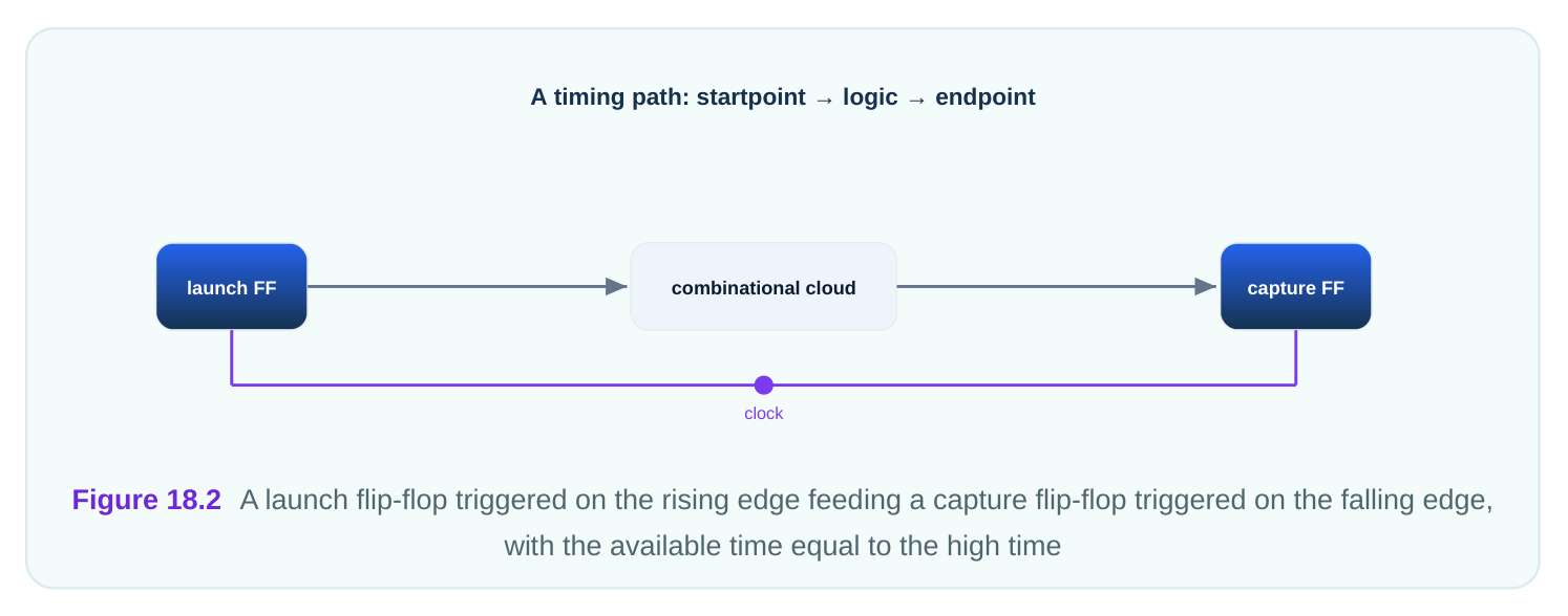
Take a clock with period 6.40 ns and a 45% duty cycle. The falling edge sits at 0.45 × 6.40 = 2.88 ns. A path that launches at the rising edge (time 0) and captures at the falling edge (time 2.88 ns) has only 2.88 ns to settle, minus setup time. If you wrongly assumed 50%, you would have planned for 3.20 ns. The 0.32 ns difference can be the line between pass and fail. Here is a small worked example.
# illustrative — names vary by tool
# Check the half-cycle window the tool will use.
report_timing -from [get_pins launch_ff/Q] \
-to [get_pins capture_ff/D] -rise_from -fall_to
# The "capture edge" line reads 2.88 ns for the 45%-duty clock.
The lesson: the falling-edge number you type is not cosmetic. It directly sets the deadline for rise-tofall paths and the start time for fall-to-rise paths.
Shifted-Edge Clocks
Sometimes the first rising edge is not at time 0. A shifted clock starts its waveform later. We do this when one clock is deliberately delayed relative to another, for example to give a slow block more margin. A shift moves both edges by the same amount. Suppose a clock has period 4.80 ns, a 50% duty cycle, and a shift of 1.20 ns. Without the shift, the waveform would be {0 2.40} . With the shift, both edges move later: rise at 1.20 ns, fall at 3.60 ns. The waveform becomes {1.20 3.60} .
# standard SDC — portable across compliant tools
# A clock shifted 1.20 ns later, still 50% duty.
create_clock -name clk_late -period 4.80 \
-waveform {1.20 3.60} [get_ports clk_late_in]
You can also describe an inverted clock through the waveform. An inverted clock falls first and rises second. To invert a balanced 4.80 ns clock, you list the falling edge before the rising edge, so the high pulse lands in the second half of the period. Most tools read the smaller number as the first edge and treat the order as "starts low" when the fall comes first. Check what your tool expects, but the underlying idea is that the order and position of the two numbers fully define the shape.
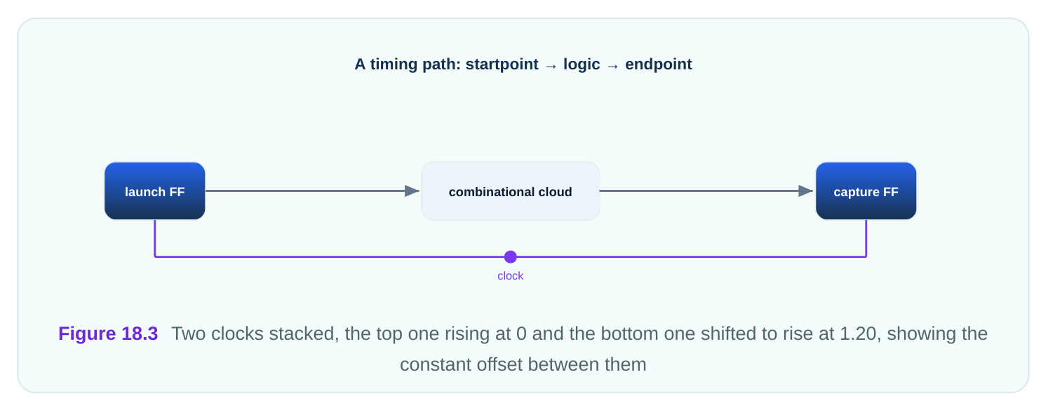
The table below compares the same base clock under different transforms.
| Transform | Period (ns) | Waveform list | First rise (ns) | First fall (ns) |
|---|---|---|---|---|
| Balanced, no shift | 4.80 | {0 2.40} | 0 | 2.40 |
| Shift +1.20 ns | 4.80 | {1.20 3.60} | 1.20 | 3.60 |
| 65% duty | 4.80 | {0 3.12} | 0 | 3.12 |
| Shift +0.60, 65% duty | 4.80 | {0.60 3.72} | 0.60 | 3.72 |
A worked check: if a shifted clock rises at 1.20 ns and a same-period unshifted clock rises at 0, the constant offset is 1.20 ns. The tool uses this offset when it pairs edges between the two clocks during analysis. Get the offset wrong by even 0.10 ns and every cross-clock check shifts with it.
Common Pitfalls
The first pitfall is leaving out the waveform when the clock is not 50%. The tool then silently assumes balanced timing. Nothing warns you. Your half-cycle paths get the wrong deadline. The second pitfall is mixing up the high time and the falling-edge time. The second number in the waveform is the time of the falling edge, not the length of the high pulse. For a clock rising at 0.50 ns with a 2.00 ns high pulse, the falling edge is at 0.50 + 2.00 = 2.50 ns, so the list is {0.50 2.50} , not {0.50 2.00} .
| Pitfall | What you typed | What you meant | Result |
|---|---|---|---|
| Missing waveform | nothing | 60% duty | Tool assumes 50% |
| High time vs edge time | {0.50 2.00} | rise 0.50, high 2.00 | Wrong fall edge |
| Forgot the shift | {0 2.40} | shift +1.20 | Cross-clock offset wrong |
| Inverted order | {2.40 0} | starts low | Tool may flip duty |
The third pitfall is forgetting that the period and the waveform must agree. If the period is 4.80 ns but you write a falling edge at 5.00 ns, the falling edge lands after the period ends. That is a contradiction. Always keep both edge numbers inside the range from 0 to one period.
Interview Q&A
rising and first falling edges in nanoseconds. The first number is the rising edge, the second is the falling edge. The tool repeats this pattern every period. For a 4.36 ns clock at 50% duty, the list is {0 2.18} .
ns period, the high time is 3.072 ns, so the waveform is {0 3.072} . The clock is then high for 3.072 ns and low for 2.048 ns each cycle.
not half the period. On a 45% duty, 6.40 ns clock, the high time is 2.88 ns, so that path has 2.88 ns instead of 3.20 ns. The shorter window can cause a setup failure.
50% duty cycle rising at 0. It checks the wrong edges for half-cycle paths and reports timing that does not match silicon. No warning is given, so the error is easy to miss.
of the falling edge, not the length of the high pulse. If the clock rises at 0.50 ns and the high pulse is 2.00 ns, the falling edge is at 2.50 ns, giving {0.50 2.50} .
4.80 ns clock with waveform {0 2.40} becomes {1.20 3.60} . The constant 1.20 ns offset is what the tool uses to pair edges with other clocks.
Key Takeaways
- A waveform is two edge times: the first rising edge and the first falling edge, repeated every period.
- Duty cycle is the high time divided by the period; a non-50% clock needs an explicit
-waveform. - The second waveform number is the falling-edge time, not the high-pulse length; mixing these up is a classic error.
- Half-cycle paths get the high time as their window, so the falling-edge position directly sets the deadline.
- A shifted clock moves both edges by the same amount and creates a constant offset the tool uses for cross-clock checks.
Comments
Leave a Reply