 ChipBuddy
← Home
ChipBuddy
← Home
Reset, Recovery & Removal Constraints
Reset, Recovery & Removal Constraints
Most timing checks look at data. They check setup and hold on normal signals. But there is another kind of check. It looks at the reset signal. A reset forces a flip-flop to a known state. A flip-flop is a small one-bit memory. Reset is how we put it in a clean state at power-up. The tricky part is releasing reset. When reset turns off, the flip-flop must wake up cleanly on the next clock edge. The release must not happen too close to that edge. If it does, the flip-flop may go into an unstable state. The checks that guard this are called recovery and removal. SDC, the timing constraint format that compliant tools read, is how we constrain these. We never expand the letters; we say SDC. This chapter covers recovery and removal, how to constrain reset deassertion, reset synchronizers, and when to false-path the reset.
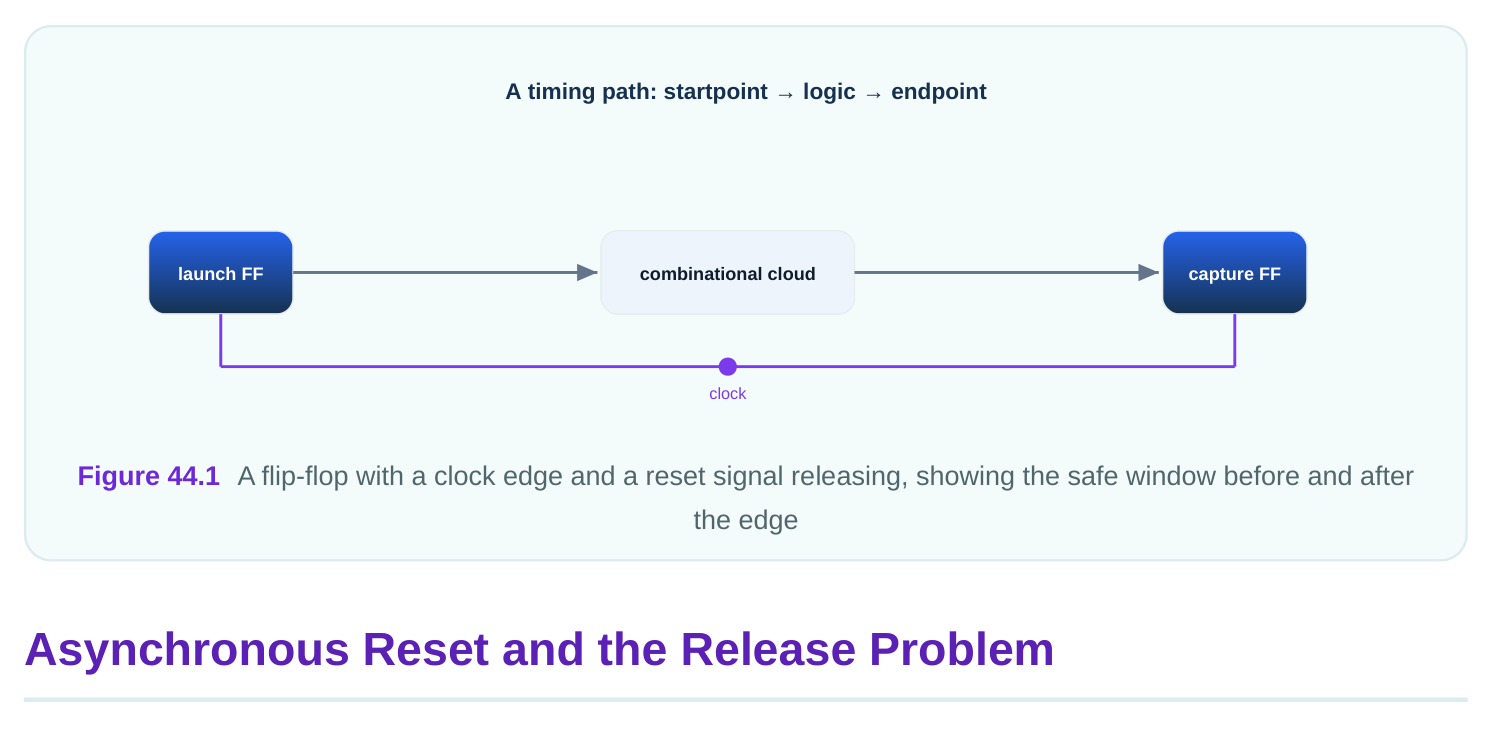
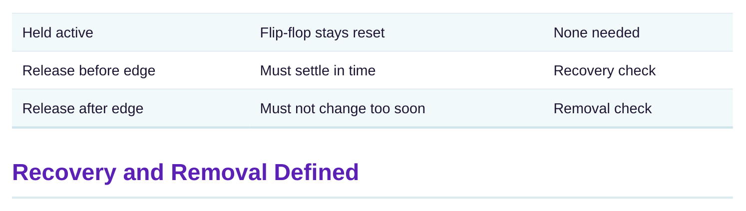
An asynchronous reset acts immediately. Asynchronous means it does not wait for a clock edge. The moment reset asserts, the flip-flop is forced to its reset value. This is good for asserting. You want the chip cleared fast, no matter the clock. But release is different. Release, also called deassertion, is when reset turns off. At release the flip-flop must return to normal clocked behavior. The first active clock edge after release decides the flip-flop's new value. If reset is still changing right at that edge, the flip-flop sees a moving input at the worst moment. It may settle to a wrong value or go metastable. Metastable means stuck between zero and one for a while. That can ripple bad data through the chip. So even an asynchronous reset has a timing rule at release. The rule is about the relationship between reset deassertion and the clock edge. There must be a safe gap. The checks that enforce the gap are recovery and removal. They are the reset world's version of setup and hold.
| Reset phase | Behavior | Timing rule |
|---|---|---|
| Assertion | Forces reset value at once | None needed |
Recovery and removal are two timing checks on the reset release. They mirror setup and hold on data. Recovery is like setup. It says reset must be released a minimum time before the active clock edge. That minimum is the recovery time. If reset releases too late, just before the edge, the flip-flop may not
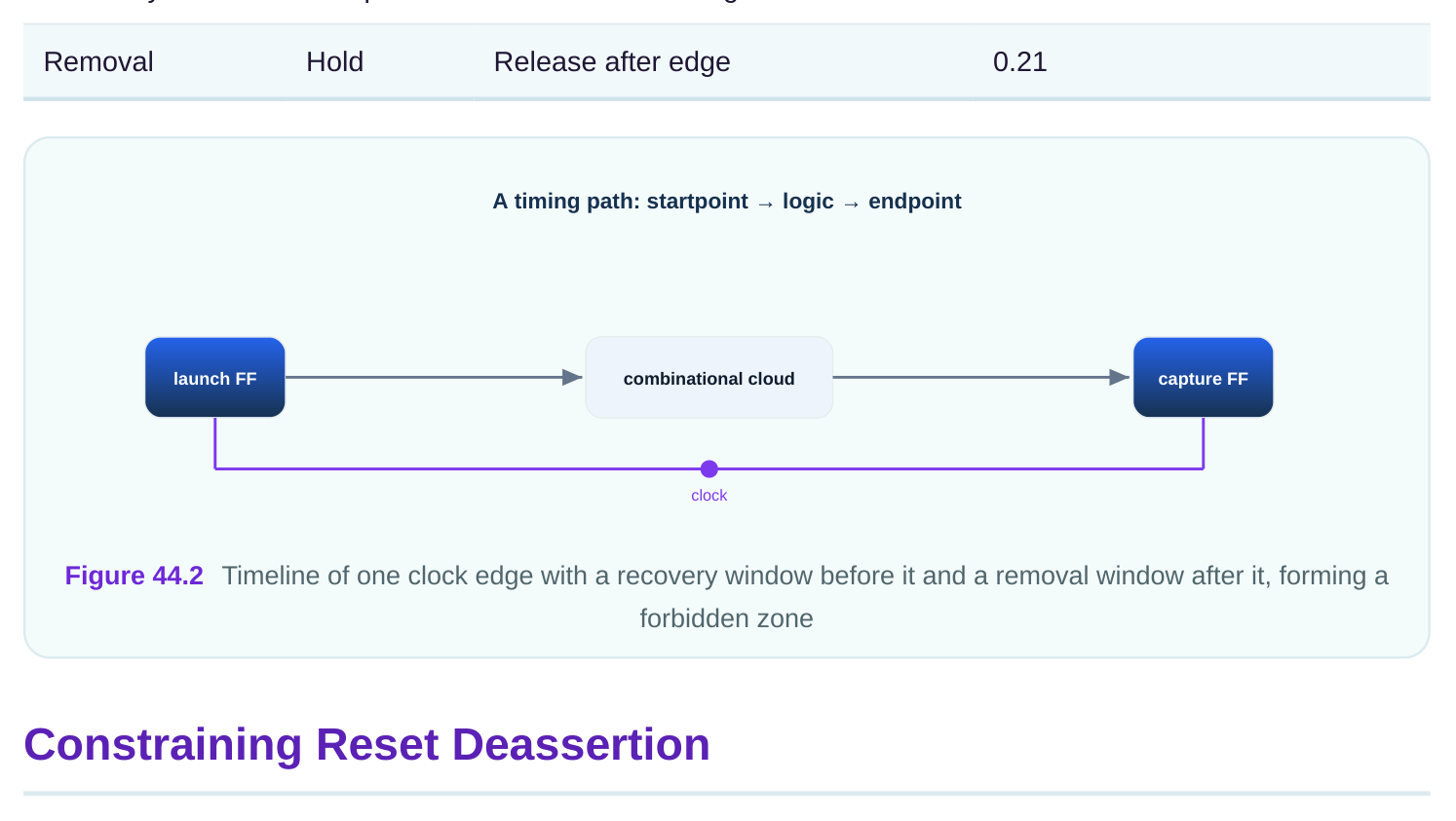
settle to normal operation in time. So recovery checks the latest safe moment for release before the edge. Removal is like hold. It says reset must stay released for a minimum time after the active clock edge, or the deassertion must come a safe time after the edge. That minimum is the removal time. If reset changes too soon after the edge, the flip-flop again sees a moving input at a bad moment. So removal checks the earliest safe moment for release after the edge. Here are made-up numbers to anchor the idea. Suppose recovery time is 0.34 ns and removal time is 0.21 ns. The clock edge is the reference. Reset release must land at least 0.34 ns before the edge to pass recovery. Or it must land at least 0.21 ns after the edge to pass removal. The window between, from 0.34 ns before to 0.21 ns after, is the danger zone. Release inside it risks metastability.
| Check | Like | Rule | Example time (ns) |
|---|---|---|---|
| Recovery | Setup | Release before edge | 0.34 |
The good news is that the timing tool checks recovery and removal on its own, once it knows the reset and the clock. You usually do not write a special command to turn them on. They come from the flipflop's reset pin and its clock. What you do constrain is the arrival of the reset signal. The reset comes from somewhere, often a pin or a synchronizer output. You tell the tool when it arrives relative to a clock. You use the same delay commands as for data, because the tool treats reset deassertion timing like a data path into the reset pin. Say the reset enters the chip on a port. You set an input delay on that port against the clock. That tells the tool when the reset edge arrives. The tool then checks recovery and removal at every flip-flop the reset reaches. The clock period here is 4.58 ns, and the reset arrives 1.12 ns after the reference edge.
# standard SDC — portable across compliant tools
create_clock -name sys_clk -period 4.58 [get_ports sys_clk]
set_input_delay -clock sys_clk 1.12 [get_ports async_rst_n]
A worked example shows how the check resolves. The clock period is 4.58 ns. Reset arrives 1.12 ns after the launching edge. The receiving flip-flop needs 0.34 ns of recovery before its capture edge. The capture edge is 4.58 ns after launch. So reset must arrive by 4.58 minus 0.34, which is 4.24 ns. It arrives at 1.12 ns plus its path delay. As long as the path delay stays under 4.24 minus 1.12, which is 3.12 ns, recovery passes. This is exactly how a setup check works, just on the reset pin.
Reset Synchronizers
Releasing a raw asynchronous reset across a big chip is risky. Different flip-flops see the release at slightly different times. Some may catch the edge, some may not. To make release clean, we use a reset synchronizer. A reset synchronizer is a small circuit. It asserts reset asynchronously, so clearing is still immediate. But it releases reset synchronously, lined up to the clock. It is usually two flip-flops in a row, clocked by the destination clock. Reset forces both to the reset state at once. When reset lifts, the release walks through the two flip-flops on clock edges. The output release is now aligned to the clock. Every downstream flip-flop sees a clean, clock-aligned release. For timing, the synchronizer changes what we constrain. The asynchronous assertion into the first stage is not a normal timed path, so it is often false-pathed. We will see that next. The synchronized output, though, is a real clocked signal. The path from the synchronizer's last flip-flop to the downstream reset pins is timed normally, with recovery and removal checked against the destination clock.
# standard SDC — portable across compliant tools
# the synchronized reset output is a real timed signal
create_clock -name dst_clk -period 3.71 [get_ports dst_clk]
# downstream recovery/removal are checked automatically on this clock
The benefit is a sharp, predictable release. Without the synchronizer, you fight recovery and removal at every flip-flop against an unaligned reset. With it, you fight them only once, at the synchronizer's clean output, and the rest of the chip follows.
| Reset style | Assertion | Release | Timing burden |
|---|---|---|---|
| Raw async | Immediate | Unaligned | Hard everywhere |
| Synchronized | Immediate | Clock-aligned | Easy after sync |
False-Pathing Asynchronous Assertion
Not every reset path should be timed. The asynchronous assertion is the clearest case. When reset asserts, it does not wait for a clock. There is no edge relationship to check on assertion. Timing it would force the tool to chase a path that has no real timing meaning. So we tell the tool to ignore it. That is a false path. A false path is a path the tool should not time. We mark it with set_false_path . For an asynchronous reset, the assertion edge into the reset pin is the candidate. The release edge still needs recovery and removal, but the asynchronous assertion does not. In practice, the path from a raw reset source into a synchronizer's asynchronous reset input is commonly false-pathed, because that input is purely asynchronous by design.
# standard SDC — portable across compliant tools
# ignore the purely asynchronous assertion into the synchronizer
set_false_path -from [get_ports async_rst_n] \
-to   [get_pins u_rst_sync/stage0_reg/CLR]
Be careful here. False-pathing the whole reset would also drop the release checks. You do not want that, because the synchronized release must still be timed. The clean approach is to false-path only the asynchronous assertion into the synchronizer, then let the synchronizer's aligned output carry normal recovery and removal downstream. A second worked example shows the trade-off. Suppose the raw reset reaches 312 flip-flops directly. Timing recovery and removal at all 312 against an unaligned reset is a mess; many will fail or need huge margins. Instead, route the raw reset only into a synchronizer. False-path that one asynchronous input. The synchronizer output, aligned to a 3.71 ns clock, then feeds the 312 flip-flops as a clean timed signal. Now the tool checks 312 ordinary recovery and removal paths against a known edge, and they close easily.
Interview Q&A
immediately with no timing rule. But release is different. The first active clock edge after release sets the flip-flop's new value. If reset changes right at that edge, the flip-flop can go metastable. So release must keep a safe gap from the edge, enforced by recovery and removal.
time before the active clock edge. Removal is like hold: reset must stay released a minimum time after the edge, or release a safe time after it. Together they define a forbidden window around the edge where release is unsafe.
once it knows the reset signal and the clock. What you constrain is the arrival of the reset, using the
same input delay or path constraints as for data. The tool then checks recovery and removal at every flip-flop the reset reaches.
but releases reset synchronously, aligned to the clock. It is usually two flip-flops in a row. This gives a clean, clock-aligned release so every downstream flip-flop sees the same edge, making recovery and removal easy to close.
assertion, typically the raw reset into a synchronizer's asynchronous input. That edge has no clock relationship, so timing it is meaningless. You must not false-path the synchronized release, which still needs recovery and removal.
removal checks on the synchronized release. The release is a real clocked signal that must be timed. Dropping its checks could let an unsafe release slip through and cause metastability downstream.
Key Takeaways
- Asynchronous reset asserts with no timing rule, but release must be timed because the flip- flop can go metastable if reset changes near the clock edge.
- Recovery mirrors setup and removal mirrors hold, defining a forbidden window around the clock edge where reset release is unsafe.
- The tool checks recovery and removal automatically once it knows the reset signal and the clock; you constrain the reset's arrival like a data path.
- A reset synchronizer asserts asynchronously but releases on the clock, giving a clean aligned release so downstream checks close easily.
- False-path only the asynchronous assertion, never the synchronized release, so the meaningless edge is ignored while real release checks stay active.
Comments
Leave a Reply