 ChipBuddy
← Home
ChipBuddy
← Home
Input & Output Delay — Multiple Clocks & Min/Max
Input & Output Delay — Multiple Clocks & Min/Max (Deep)
A chip rarely lives alone. Signals arrive at its pins after traveling through other chips. Signals leave its pins and travel into still more chips. The timing tool cannot see those other chips. So you must describe their behavior at the boundary. You do this with input delay and output delay. This chapter goes deep on the hard cases: many delays at one pin, different clocks, different edges, and the split between minimum and maximum values. We keep the format generic. We call it SDC. We never name a tool. We say "the timing tool" for the engine that checks paths. We say "the synthesis tool" for the engine that builds logic.
Why One Pin May Need Several Delays
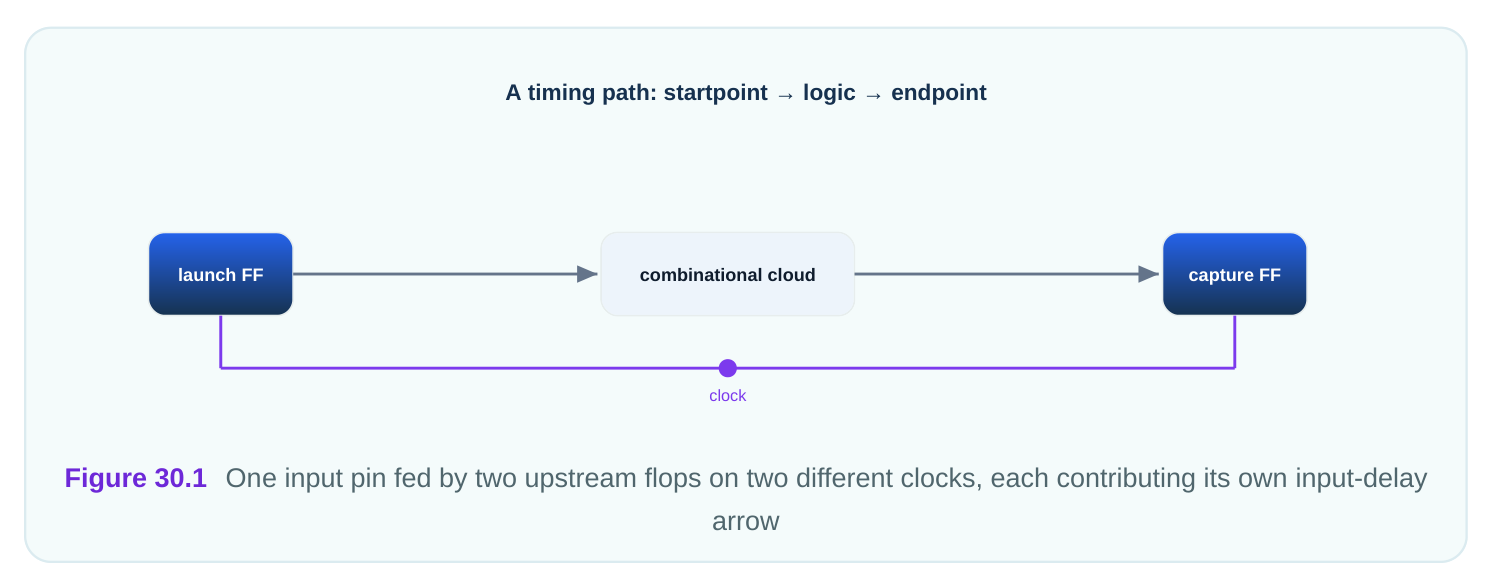
An input pin is a door. Data walks through it. But the data may come from more than one source. One source may be clocked by a fast clock. Another source may be clocked by a slow clock. Each source has its own launch timing. So each source needs its own delay number at the same pin. The command set_input_delay describes how late a signal arrives at an input pin, measured against a clock edge. By default, a second call to the same pin replaces the first. That is a trap. If you want both numbers to live together, you must say so. The option -add_delay tells the tool to keep the existing delay and add a new one beside it.
Here is the mental picture. A pin named data_rx is fed by two upstream blocks. One block runs on a clock we call clk_core . One runs on a clock we call clk_aux . Without -add_delay , the second constraint erases the first. With it, both survive. The tool then checks the pin against both clocks.
The same logic applies to output delay. An output pin may feed two downstream blocks. Each downstream block has its own setup and hold need. So the output pin may carry two output delays, one per clock.
Max for Setup, Min for Hold
Timing has two questions. Will the data arrive in time to be caught? That is setup. Will the data stay still long enough after the edge? That is hold. The two questions pull in opposite directions. Setup fears slow data. Slow data may miss the capture edge. So setup uses the largest, latest arrival. That is the maximum delay. Hold fears fast data. Fast data may race ahead and corrupt the previous value. So hold uses the smallest, earliest arrival. That is the minimum delay. The option -max sets the number used for setup checks. The option -min sets the number used for hold checks. If you give only one number with neither option, the tool uses it for both. That is convenient but rough. Real designs split the two.
| Check | Fears | Uses delay | Option |
|---|---|---|---|
| Setup | Late data | Maximum | -max |
| Hold | Early data | Minimum | -min |
| Both (single value) | Generic | Same number twice | neither |
A worked feel for the split: suppose data leaves an upstream flop. Through a fast process corner it arrives 0.83 ns after the edge. Through a slow corner it arrives 2.67 ns after the edge. You give -min 0.83 and -max 2.67 . Hold uses 0.83. Setup uses 2.67. Each check sees the corner that hurts it most.
Several Clocks at the Same Boundary
When two clocks touch one pin, the tool builds a check for each clock against each related edge. This grows fast. Two input clocks and two output clocks can yield many path groups. You do not write all of them. You write the delays. The tool forms the cross-product of checks. The key rule is edge awareness. set_input_delay and set_output_delay both accept a clock and, through -clock_fall , a choice of which clock edge launched or captured the data. By default, the rising edge is used. If the upstream logic launched on the falling edge, you must say -clock_fall . Otherwise the tool measures against the wrong reference and your numbers are silently wrong.
| Option | Meaning | Default |
|---|---|---|
| -clock <name> | Which clock the delay is measured against | required |
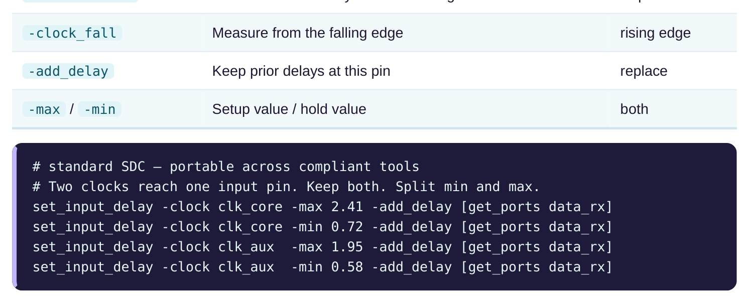
Notice the pattern. Four lines describe one pin. Two clocks. Each clock gets a max and a min. The - add_delay flag is on every line after the first, so nothing is erased.
# standard SDC — portable across compliant tools
# Output pin feeds two downstream blocks. One captures on the falling edge.
set_output_delay -clock clk_core -max 1.34 [get_ports result_tx]
set_output_delay -clock clk_aux -clock_fall -max 1.07 -add_delay [get_ports
result_tx]
set_output_delay -clock clk_aux -clock_fall -min 0.41 -add_delay [get_ports
result_tx]
How the Tool Picks the Worst Case
When many delays sit on one pin, the tool does not average them. It does not pick the first one. It evaluates every path that the delays create and reports the one with the least slack. Slack is the margin between when a signal is needed and when it actually arrives. Positive slack is good. Negative slack is a violation.
For setup, the tool tries each max delay against each related capture edge. The combination that yields the smallest setup slack wins the report. For hold, the tool tries each min delay against each related edge. Again the smallest slack wins.
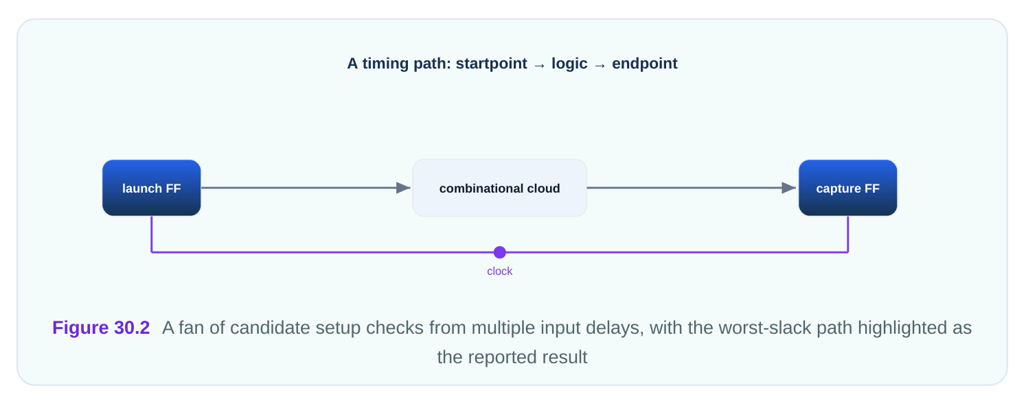
This is why you must enter both clocks honestly. If you drop the clk_aux delay because it "seemed smaller," you may hide the very path that fails in silicon. The tool can only protect paths you describe. A small worked illustration. On pin data_rx the setup checks resolve like this against a capture period:
| Source clock | Input max delay | Path delay inside chip | Required time | Arrival time | Slack |
|---|---|---|---|---|---|
| clk_core | 2.41 | 1.18 | 4.90 | 3.59 | +1.31 |
| clk_aux | 1.95 | 1.18 | 3.70 | 3.13 | +0.57 |
The tool reports +0.57 ns as the setup result for that pin, because it is the smaller margin. If you had omitted the clk_aux line, the report would have shown a comfortable +1.31 ns and hidden the tighter path.
Virtual Clocks and Boundary Hygiene
Sometimes the upstream chip's clock has no real pin on your chip. You still need a reference for the input delay. The answer is a virtual clock. A virtual clock is a clock with a waveform and period but no source pin. It exists only as a timing reference. You create it once, then point input or output delays at it. This keeps the boundary honest even when the launching clock never enters your design. The pattern below uses a virtual clock to anchor an output delay.
# standard SDC — portable across compliant tools
create_clock -name clk_virt_io -period 6.30
set_output_delay -clock clk_virt_io -max 2.18 [get_ports status_tx]
set_output_delay -clock clk_virt_io -min 0.66 -add_delay [get_ports status_tx]
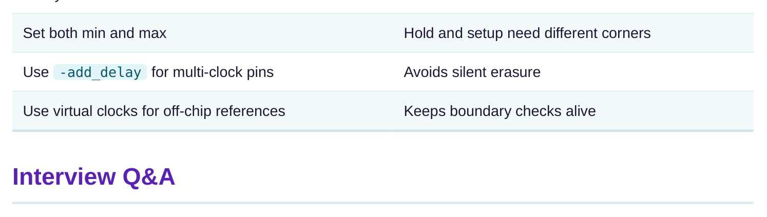
Good boundary hygiene has a few habits. Always set both -max and -min , even if you start with the same number. Always name the clock. Use -add_delay whenever a pin can be reached from more than one clock. Reserve plain replacement for the rare case where you truly want to overwrite. These habits make the report trustworthy.
| Habit | Why it matters |
|---|---|
| Always name a clock | No reference means no real check |
the pin may be driven by several upstream sources on different clocks or edges. Each source launches data with its own timing. Each needs its own delay number. Without separate entries, the tool checks only one launch story and misses the others.
existing delays on the pin and add the new one beside them. If you forget it, the new constraint replaces the old one. You can silently lose a clock's delay and never see the path it would have created.
data arrives too late to be captured, so it tests the latest possible arrival, the maximum. Hold worries that data arrives too early and corrupts the prior value, so it tests the earliest arrival, the minimum. Each check picks the corner that stresses it most.
launched or will be captured on the falling edge of the clock rather than the rising edge. The default reference is the rising edge. If the real silicon uses the falling edge, you must say -clock_fall or the measurement is taken against the wrong reference.
every path the delays create and reports the path with the least slack. It does not average or pick arbitrarily. The worst margin wins the report, which is exactly the path most likely to fail.
and period but no source pin. It is used as a timing reference for input or output delays when the launching or capturing clock never physically enters your design. It keeps boundary checks meaningful in that case.
Key Takeaways
- One pin can carry many delays. Different upstream or downstream clocks and edges each need their own number at the same boundary.
-add_delayprevents silent erasure. Without it, a second constraint overwrites the first, and a real path can vanish from the report.- Max feeds setup, min feeds hold. Always set both, because the two checks fear opposite corners of arrival timing.
- Edge selection matters. Use
-clock_fallwhenever the real launch or capture happens on the falling edge, or the reference is wrong. - The tool reports the worst slack. It tries every candidate path the delays create, so honest, complete delays are what keep silicon safe.
Comments
Leave a Reply