 ChipBuddy
← Home
ChipBuddy
← Home
Interview Q&A Bank
Interview Q&A Bank
This bank collects the questions that come up most in timing-constraint interviews. They are grouped by topic so you can study one area at a time. Each answer is short and uses real numbers where a number makes the idea concrete. Read the question, try to answer aloud, then check yourself against the text.
How to Use This Bank
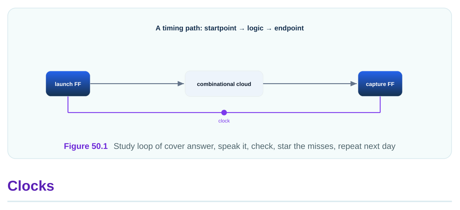
Work through one topic group at a time rather than jumping around. Cover the answer, say yours out loud as if to an interviewer, then compare. The best answers are short and include a concrete number: "an 8.00 ns period for 125 MHz," not just "a period." If a question has a worked number, make sure you can reproduce the arithmetic, because interviewers love to change one value and ask you to redo it. Star the ones you miss and return to them the next day.
and a waveform so it knows when launch and capture edges occur. Without it, the logic on that clock is not timed at all. Example: create_clock -period 4.00 defines a 250 MHz clock.
frequency in megahertz. So 200 MHz is 1000 / 200 = 5.00 ns, and 333 MHz is about 3.00 ns. The period is what create_clock takes, not the frequency.
flip-flops. If the launch flop sees the edge at 0.00 ns and the capture flop sees it at 0.12 ns, the skew is 0.12 ns. Skew can help or hurt a path depending on its direction.
splits into source latency, from the true origin to the clock port, and network latency, from the port through the on-chip tree. Early flows model it as a single number before the tree is built.
every flip-flop at the same instant with zero skew and no tree delay. A propagated clock uses the real built-tree delays, so flops see the edge at slightly different times, producing real skew. Sign-off uses propagated clocks.
half the period, a 50 percent duty cycle. For a 4.00 ns period that is a rising edge at 0.00 ns and a falling edge at 2.00 ns. You can override with an explicit waveform.
listing the rise and fall times. For a 10.00 ns period that is high for 3.00 ns, you specify rise at 0.00 and fall at 3.00. This matters for paths launched or captured on the falling edge.
a timing reference. It is used to describe the timing of external logic for I/O delays when that clock never physically enters the chip. You reference it in set_input_delay and set_output_delay .
Generated Clocks
independently. A divide-by-two of a 5.00 ns clock becomes a 10.00 ns generated clock. It automatically tracks changes in its source, which independent clocks do not.
source. If the source period changes from 5.00 to 4.80 ns, the divided clock updates automatically. Two independent declarations drift apart the moment one is edited and the other is forgotten.
from the source clock, applied at the divider's output pin. A 2.00 ns source becomes an 8.00 ns generated clock. The tool then times that domain against the 8.00 ns period.
source, as from an on-chip clock generator. A 10.00 ns input multiplied by 5 yields a 2.00 ns, 500 MHz generated clock. The source is the input clock that feeds the generator.
go unchecked, or get the wrong clock and are checked against the wrong period. A divide-by-two path checked against the fast source period looks like a severe failure; checked against nothing looks perfect. Both are wrong.
respect to its source, modeling a clock that is flipped in phase. This changes which edges count as launch and capture. The period stays the same; the edges shift by half a period.
source's timing but can carry additional latency for the path through the generating logic. This models the extra delay the divider or generator adds before the new clock reaches its loads.
Port Delays
becomes valid at the port, accounting for the external logic and board that drive it. For a 5.00 ns clock, an input delay of 2.40 ns means the on-chip logic has 2.60 ns left to capture.
logic downstream needs after the chip's output changes. An output delay of 1.90 ns on a 5.00 ns clock leaves 3.10 ns for the on-chip path to produce the output.
latest arrival and drives the setup check. Min delay models the best-case earliest arrival and drives the hold check. An input might be max 2.40 ns and min 0.60 ns, framing both the late and early edges.
to measure from. The referenced clock fixes when the launch or capture happens. Referencing the wrong clock measures arrival against the wrong edge and produces meaningless slack.
as the reference. It represents the external clock that times the source logic even though it never enters the chip. The input delay is then measured relative to that virtual clock.
is left unconstrained, then overriding specific ports with real numbers. This prevents the silent danger of a port with no delay being skipped entirely from analysis.
5.50 equals 2.50 ns for the on-chip path from the port to the capturing flip-flop, before subtracting setup and any skew. If the on-chip logic needs more than 2.50 ns, the path fails setup.
the period the external receiver consumes after your output changes. The tool subtracts it from the period to find how much time your internal path has to produce the output.
Exceptions
should not be timed. Declaring it with set_false_path removes it from analysis. A common example is a path crossing between two truly asynchronous clocks.
configuration signal, a path between unrelated clocks handled by a synchronizer, or a path active only in a mode you do not analyze. Never use it to hide a real violation you simply cannot fix.
If you mark a path false that is actually real, a genuine violation goes unseen and reaches silicon. False paths must be justified by function, not convenience.
unrelated, so the tool does not time any path crossing between groups. This is cleaner than many individual false paths when entire clock domains are independent, as on a chip bridging several interfaces.
set_clock_groups handles all cross-domain paths between the named groups in one statement andstays correct as the design grows. Individual false paths must enumerate every pair and are easy to leave incomplete. Groups scale; piecemeal false paths do not.
path, and both beat a plain max-delay setting. A more specific exception beats a more general one.
When two exceptions overlap, the higher-priority and more specific one wins, so know which command dominates.
one specific path while leaving the rest of those endpoints' paths checked. This is more precise than disabling a whole clock relationship and avoids hiding neighboring real paths.
Multicycle
data is only sampled every few cycles. A multicycle of 3 on a 4.00 ns clock gives the path 12.00 ns for setup instead of 4.00 ns.
cycle: a slow arithmetic block whose output is used only every third cycle, or a register loaded only on certain enables. Timing them at one cycle would over-constrain them needlessly.
check one full extra cycle after the relaxed capture edge, demanding an impossible hold. You must also relax hold, normally to N minus 1, to pull the hold check back to the right edge.
This moves the hold check to one cycle after launch rather than four cycles, the correct relationship. On a 5.00 ns clock that is a hold edge at 5.00 ns, not 20.00 ns.
ns, for the setup check instead of one period of 6.00 ns. The path may take up to 12.00 ns minus setup and skew. The accompanying hold should be set to 1.
the multiplier interacts with both clocks' edges. You must reason carefully about which clock the cycle count applies to. Cross-clock multicycle paths are a frequent source of subtle errors.
is too strict, often creating hold violations that look unfixable. Designers chasing these phantom hold failures often miss that the real fix is adding the N minus 1 hold line.
entire domain and all its checks. A multicycle path relaxes only the specific path you target, leaving the rest of the domain at full speed. It is a surgical relaxation, not a global one.
MMMC
configuration like normal versus test. Corner is a physical condition like slow-cold versus fast-hot. MMMC analyzes the design across the combinations so it works in every mode at every corner.
voltage corner stresses setup, while a fast, hot or high-voltage corner stresses hold. A chip that passes only one corner can fail in the field. You must cover the worst of each.
low voltage and the temperature that maximizes delay, usually limits setup because paths are slowest. The fast corner, fast silicon, usually limits hold because data races through and can arrive too early. You check both.
as a normal operating mode and a scan-test mode. Each mode may use different clocks, different case-analysis settings, and different exceptions, so each needs its own constraint view.
the number of combinations grows quickly and a flow that handles them together guarantees none is forgotten. Checking by hand invites missing a mode-corner pair where the chip actually fails. MMMC makes the coverage systematic.
main clock live in a shared file every mode reads, while mode-specific items like case analysis live in per-mode files. This keeps the shared parts consistent and reduces duplication across modes.
Constraint Management
synthesis, placement, routing, and timing all judge the design identically. One edit propagates everywhere, and the chip you tape out matches the chip you analyzed.
block's pins, internal paths, and budgeted I/O delays. Top constraints define clocks at their true source, use real I/O delays, and add cross-block exceptions. The block's estimates must be reconciled with top-level reality.
must fit into shares: source block internal, wire, destination block internal. Each share becomes an input or output delay, and all shares must sum to the full period. For 2.50 ns you might use 0.90, 0.40, and 1.20.
results, and the commit history shows which edit caused a timing change between runs. Without history you cannot tell whether a regression came from the design or from a quietly changed constraint number.
report unconstrained ports and paths, and confirm every generated clock is declared. A clean timing report on an incomplete constraint set is the real hazard, so coverage is verified before reading slack.
never checked and so passes silently while it may be far too slow. A failing path is honest and gets fixed; a path that was never analyzed walks straight into silicon as hidden risk.
Comments
Leave a Reply