 ChipBuddy
← Home
ChipBuddy
← Home
The Synthesis & Timing Flow
The Big Picture of the Flow
A chip travels through several steps before it becomes silicon. The flow starts with RTL (registertransfer-level code, the design written in a hardware language). It ends with sign-off (the final timing check before manufacturing). The same SDC constraint file rides along the whole way. The main steps are RTL, synthesis, place-and-route, and sign-off. Synthesis turns RTL into a gate netlist (a list of real logic cells and how they connect). Place-and-route (the step that positions cells and draws wires) builds the physical layout. Sign-off confirms timing on that final layout. Constraints act at every step. They are not a one-time setting. Each tool reads the SDC, applies the same timing rules, and works to meet them. This is why a clean, consistent SDC matters so much.
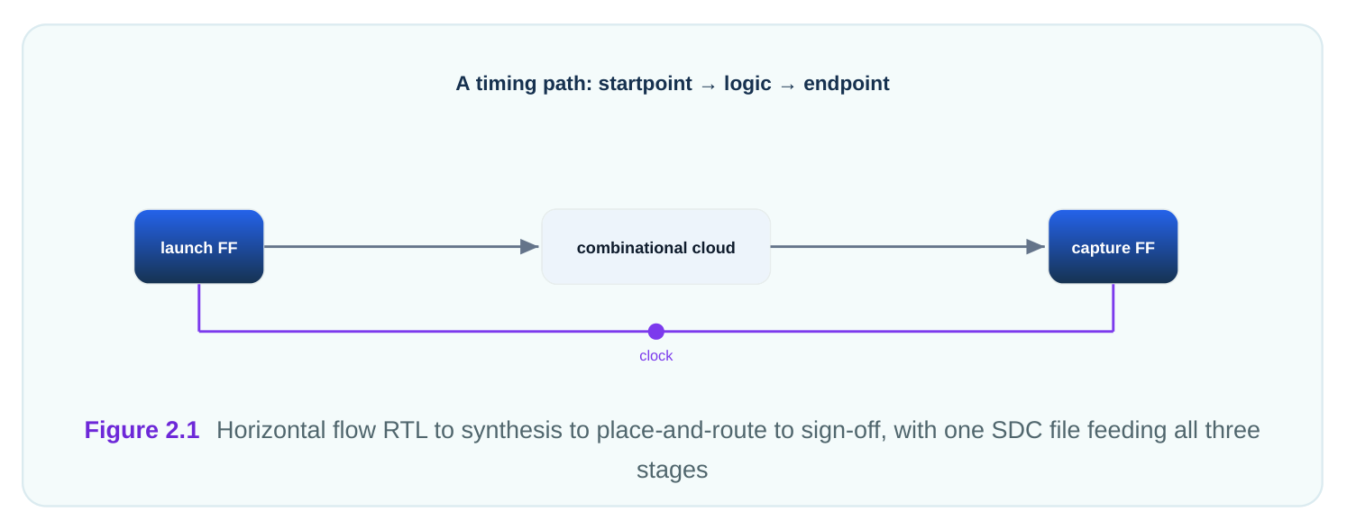
The order is deliberate. Early steps make rough estimates. Later steps use real physical data. The SDC stays the same so the target never drifts between steps.
What Synthesis Does With Constraints
The synthesis tool turns RTL into gates, and it uses constraints to choose how. Without a clock declaration it cannot tell which paths matter. With the clock period set to, say, 3.2 ns, it knows the budget for every register-to-register path. Synthesis is an optimizer. It tries many gate choices to fit the timing budget. For a tight path it may pick faster, larger cells. For a relaxed path it may pick smaller cells to save power and area. The constraints set the target it optimizes toward. Buffering is a key tool here. A buffer (a cell that strengthens or delays a signal) helps a weak driver reach a far or heavy load. The synthesis tool inserts buffers when a path is slow or a signal must fan out (drive many gates). It does this only because constraints told it the path must be fast. Constraints also shape the interface. Input and output delays tell synthesis how much time the outside world consumes. The tool then knows how much time is left inside the chip and sizes the boundary logic to fit.
| Constraint type | What synthesis does with it |
|---|---|
| Clock period | Sets the budget for every register-to-register path |
| Input delay | Reserves time for upstream logic, leaving the rest inside |
| Output delay | Reserves time for downstream logic before the next capture |
| Max transition | Limits how slowly a signal may switch, adds buffers if needed |
| False path | Skips a path, freeing the tool from optimizing it |
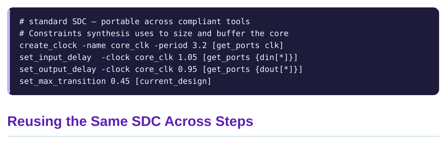
The same SDC file is reused at each step, and that is the point. One source of truth keeps the target identical from synthesis through sign-off. If every step optimized to a different number, the chip would never converge.
Reuse does not mean the file never grows. Early on, the SDC describes intent at a high level. As physical detail appears, you may add or refine commands. But the core promise, like a 3.2 ns clock, stays fixed. Each step gives better timing accuracy. Synthesis estimates wire delay before wires exist, using rough models. Place-and-route measures real wire length. Sign-off uses the most accurate models of all. The SDC is the constant; the accuracy of the answer improves.
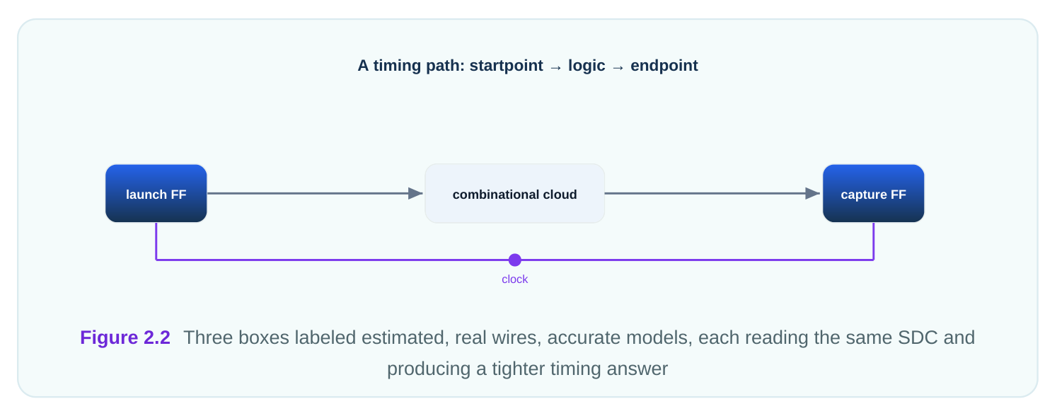
This is why a path can pass at synthesis and fail at place-and-route. The target did not change. The wire delays became real, and a path that looked fine on estimates now misses. The SDC reuse makes the regression easy to spot.
What Place-and-Route Does With Constraints
The place-and-route tool reads the same SDC, then fixes timing using physical reality. Now wires have real length, and length adds delay. A path that was comfortable on estimates may now violate its budget. The tool reacts by moving cells closer, resizing them, or adding buffers along long wires. Every action aims at the constraint target. A long wire driving a heavy load is a classic case: the tool splits it with buffers so each segment meets the transition and delay limits. Clock distribution gets special care here. The tool builds the clock network so edges reach all flip-flops at nearly the same time. Clock skew (the difference in clock arrival between two flip-flops) and clock latency (the delay from clock source to a flip-flop) both come from this network, and both feed the timing checks.
# standard SDC — portable across compliant tools
# Clock-network expectations used during place-and-route
set_clock_latency      -source 0.30 [get_clocks core_clk]
set_clock_uncertainty  0.12 [get_clocks core_clk]
set_clock_transition   0.08 [get_clocks core_clk]
Here uncertainty (a safety margin covering jitter and modeling error) of 0.12 ns is subtracted from every setup check. The tool must beat the target by that margin, so it builds the network and logic with that buffer in mind.
Sign-Off and Checking the Result
Sign-off is the final, most accurate timing check. It reuses the SDC one last time on the finished layout. If the design meets timing here, the contract is satisfied and the chip can go to manufacturing. At sign-off you run reports to inspect the worst paths. Reporting commands vary between tools, but they all answer the same questions: which path is slowest, what is its slack, and which clock does it belong to. The SDC defines what "slow" even means.
# illustrative — names vary by tool
report_timing -delay_type max -max_paths 5
# Shows the five worst setup paths, each with a startpoint,
# an endpoint, an arrival time, a required time, and a slack.
Here is how the same path tightens across steps as wire data improves, all against the same 3.2 ns clock.
# worked example — one path across the flow (3.2 ns clock)
Synthesis (estimated wires):  arrival 2.70 ns -> slack +0.50 ns
Place-and-route (real wires): arrival 3.05 ns -> slack +0.15 ns
Sign-off (accurate models):   arrival 3.18 ns -> slack +0.02 ns
Slack shrinks from 0.50 ns to 0.02 ns, yet the target never moved. The SDC stayed constant; only the accuracy of the wire and cell delays improved. The path still passes, barely, at sign-off.
| Step | Wire model | Typical action | Accuracy |
|---|---|---|---|
| Synthesis | Estimated | Pick cell sizes, early buffers | Low |
| Place-and-route | Real length | Move cells, add buffers, build clock tree | Medium |
| Sign-off | Detailed | Verify and report only | High |
Interview Q&A
place-and-route, and sign-off. They are not a one-time setting. Each tool reads the same SDC and optimizes or checks against the same target.
step used a different target, the design would never converge. Reusing the file means a 3.2 ns clock stays 3.2 ns from synthesis through sign-off, and only the accuracy of the analysis improves.
to-register path. With a 3.2 ns clock, it sizes cells and inserts buffers so each path fits inside 3.2 ns. Relaxed paths get smaller cells to save power and area.
the wire delays became real. Synthesis estimates wire delay before wires exist; place-and-route measures real length. A path comfortable on estimates can miss once true wire delay is added.
real wire lengths and a real clock network. It moves cells, resizes them, and adds buffers along long wires, and it builds the clock tree that determines skew and latency.
layout, using the same SDC. You run reports to find the worst paths and their slack. If timing is met here, the chip can be manufactured.
Key Takeaways
- The flow is RTL to synthesis to place-and-route to sign-off, and the same SDC feeds every timing step.
- Synthesis optimizes toward the constraints, choosing cell sizes and inserting buffers to fit the clock budget.
- Reusing one SDC keeps a single source of truth so the target never drifts between steps.
- Accuracy improves down the flow: estimated wires, then real wires, then detailed sign-off models, while the target stays fixed.
- A path can pass early and fail later as wire delays become real, which is exactly why reuse makes regressions easy to catch.
Comments
Leave a Reply