 ChipBuddy
← Home
ChipBuddy
← Home
Timing Analysis Basics — Paths, Setup & Hold
What a Timing Path Is
A timing path is a route a signal travels from where it starts to where it lands. The timing tool (the program that checks if a chip meets its speed goals) breaks the whole design into millions of these paths. It then checks each one. Every path has a startpoint and an endpoint. A startpoint is where a value launches: usually a flip-flop's output or an input port (a pin where signals enter the chip). An endpoint is where a value is captured: usually a flip-flop's data input or an output port (a pin where signals leave). A flip-flop (a tiny storage cell that grabs a value on a clock edge) is the anchor for most paths. Data leaves one flip-flop on a clock edge, travels through some gates, and must arrive at the next flip-flop before the next clock edge. That trip is the path.
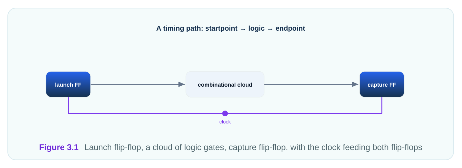
The delay of a path is the sum of every cell delay and every wire delay along it. If the gates and wires add up to 2.85 ns, the path takes 2.85 ns to settle. Whether that is fast enough depends on the clock.
The Four Kinds of Paths
Paths come in four families, based on their two endpoints. Knowing the family tells you which clocks are involved and which checks apply. The first family is register to register. Data goes from one flip-flop to another, both inside the chip. This is the most common path and the core of timing analysis. The clock paces both ends. The second is input to register. Data enters at an input port and lands at a flip-flop. The path starts outside the chip, so you must say when external data arrives, using an input delay. The third is register to output. Data leaves a flip-flop and exits at an output port. The path ends outside the chip, so you must say when the outside world needs the data, using an output delay. The fourth is input to output. Data passes straight through, port to port, with no flip-flop in between. These combinational paths (logic with no storage) are less common but still need timing rules.
| Path family | Startpoint | Endpoint | Boundary constraint needed |
|---|---|---|---|
| Register to register | Flip-flop | Flip-flop | None (internal) |
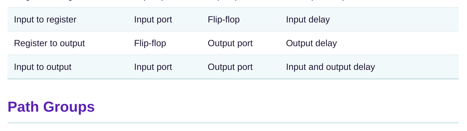
The tool sorts paths into path groups so reports stay organized. A path group is a bucket of related paths, usually grouped by the clock at the endpoint. Each clock gets its own group by default.
Grouping matters for two reasons. First, it makes reports readable: you can ask for the worst path per group instead of one giant list. Second, the optimizer can give each group its own effort, so a critical clock gets priority. You can also create custom groups for special logic, like the input paths or a specific block. This lets you watch one part of the design closely without noise from the rest.
Three numbers decide whether a path passes. Arrival time is when the signal actually shows up at the endpoint. Required time is the deadline, the latest the signal is allowed to show up. Slack is the difference between them. Slack is the headline number. Slack equals required time minus arrival time. Positive slack means the path passes with room to spare. Negative slack means the path fails by that amount. Zero slack means it just barely makes it.
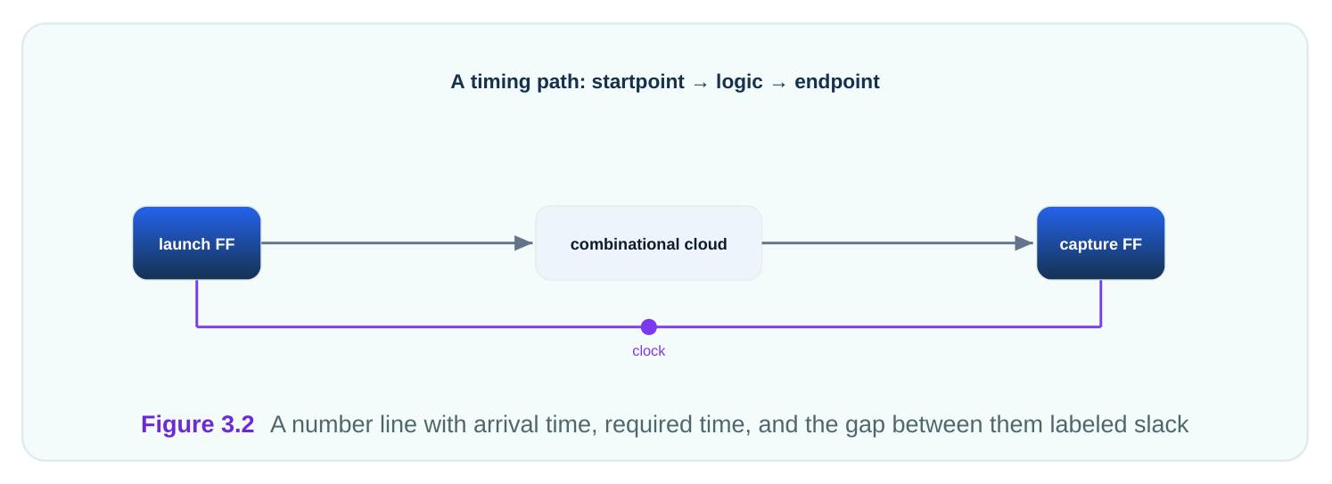
The clock sets the required time. If the clock period is 3.2 ns, the next capture edge is 3.2 ns after the launch edge. The data must arrive before that edge, minus a small setup time. That deadline becomes the required time.
# worked example — register-to-register slack (3.2 ns clock)
Launch edge at:            0.00 ns
Capture edge at:           3.20 ns
Setup time of flip-flop:   0.10 ns
Required time = 3.20 - 0.10 = 3.10 ns
Data arrival at endpoint:  2.85 ns
Slack = required - arrival = 3.10 - 2.85 = +0.25 ns  (PASSES)
This path passes with 0.25 ns to spare. If the logic were slower and arrival rose to 3.40 ns, slack would be 3.10 minus 3.40, or negative 0.30 ns, and the path would fail.
Setup and Hold Checks
Every flip-flop demands two things to capture data safely. Data must be stable a little before the clock edge, and stable a little after it. These two demands become the setup check and the hold check. The setup check asks: did data arrive early enough? Setup time (the quiet window before the clock edge) must be respected. A setup failure means the path is too slow; the data arrived after the deadline. Setup is the "fast enough?" check. The hold check asks: did data stay stable long enough after the edge? Hold time (the quiet window after the clock edge) must be respected. A hold failure means a path is too fast; new data raced through and changed the value before it was safely captured. Hold is the "not too fast?" check. The two checks use different clock edges as their reference. Setup compares against the next clock edge, one period later. Hold compares against the same clock edge that launched the data. This is why fixing one can disturb the other.
| Check | Question | Failing cause | Reference edge |
|---|---|---|---|
| Setup | Is the path fast enough? | Path too slow | Next edge (one period later) |
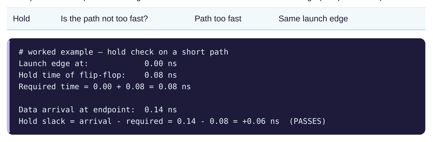
Note the hold slack formula flips: it is arrival minus required, because hold wants data to arrive late
enough, not early. Here data settles at 0.14 ns, safely after the 0.08 ns hold window, so the value is captured cleanly. Setup failures are usually fixed by speeding the path up: smaller logic, faster cells, shorter wires. Hold failures are usually fixed by slowing a path down: adding small delay buffers. Both checks must pass at the same time for a working chip.
Interview Q&A
gates and wires. The startpoint is usually a flip-flop output or input port; the endpoint is a flip-flop data input or output port. The path's delay is the sum of all cell and wire delays along it.
slack means the path passes with margin; negative slack means it fails by that amount. For example, a required time of 3.10 ns and arrival of 2.85 ns gives +0.25 ns of slack.
enough; it compares against the next clock edge one period later. Hold asks if the path is not too fast; it compares against the same edge that launched the data. Setup failures mean too slow, hold failures mean too fast.
capture edge, so it references the edge one period later. Hold data must stay stable just after the launching edge, so it references that same edge. This is why fixing setup can break hold and vice versa.
reports are readable and the optimizer can prioritize. You can ask for the worst path per group instead of scanning one huge list, and custom groups let you watch specific logic.
path up: faster cells, smaller logic, shorter wires. Hold failures are fixed by slowing a path down, usually by adding small delay buffers. Both must pass at once for a working chip.
Key Takeaways
- A timing path runs from a startpoint to an endpoint, and its delay is the sum of all cell and wire delays along it.
- Paths fall into four families by endpoint; input and output delays are needed wherever a path touches a port.
- Slack = required time minus arrival time; positive passes, negative fails, and it is the headline timing number.
- Setup checks "fast enough" against the next edge; hold checks "not too fast" against the same launch edge.
- Setup is fixed by speeding paths up, hold by slowing paths down, and both must pass together.
Comments
Leave a Reply