 ChipBuddy
← Home
ChipBuddy
← Home
Input & Output Delays
Input & Output Delays
A chip never works alone. Data arrives at its input pins from other chips, and leaves its output pins toward other chips. The timing tool can only see inside our chip. It does not know how long the outside world takes. We must tell it. The SDC constraint format does this with two commands:
set_input_delay and set_output_delay .An input pin is where a signal enters the chip; here we call it an input port. An output port is where a signal leaves. A port is just a top-level connection point. Both commands describe off-chip timing measured against a clock edge, so the tool can finish the setup and hold checks for paths that cross the chip boundary. This chapter explains how to model that off-chip time, why we split the clock period between inside and outside the chip, how max and min values feed setup and hold, and what a virtual clock is. The mental model to hold onto is a relay race. The clock period is the total time allowed for one lap. The off-chip device runs the first part of the lap and hands the baton to our input port. Our internal logic runs the middle part. At the output, our chip hands the baton back to the next device, which runs the final part. Input and output delays describe the legs that other chips run. If we never describe those legs, the tool assumes our chip gets the whole lap to itself, which is never true at the boundary.
Modeling Off-Chip Timing Against a Clock
Every external signal is launched or captured by some clock, even if that clock lives on another chip. The input delay is the time from the launching clock edge to the moment data arrives at our input port. The output delay is the time our data must be stable at the output port before the capturing clock edge on the other chip.
set_input_delay says: relative to this clock, the data shows up at the port this many nanosecondsafter the edge. The tool then knows how much of the period is already used up outside, and how much is left for the path inside our chip.
set_output_delay says: the external chip needs the data this many nanoseconds before itscapturing edge. That number is the external setup time plus the external wire delay. The tool subtracts it from the period to know the deadline at our output port.
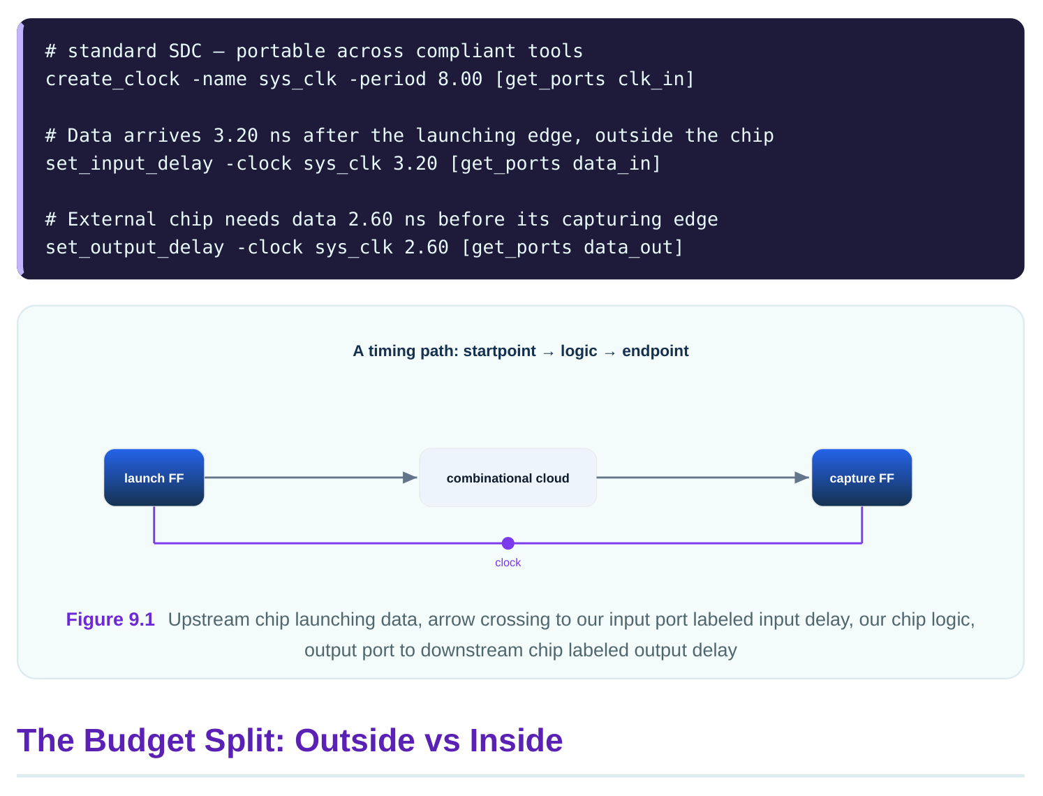
Think of the clock period as a fixed budget. For an input path, part of that budget is spent outside the chip before the data even reaches us. The rest is what our internal logic is allowed to use. The input delay is exactly the outside portion. With an 8.00 ns period and a 3.20 ns input delay, the inside logic has at most 8.00 - 3.20 = 4.80 ns, minus the capture flip-flop's setup time. If our internal path is faster than that, we pass.
Output paths split the budget the other way. The output delay is the part of the period the downstream chip reserves for itself. With an 8.00 ns period and a 2.60 ns output delay, our internal logic plus launch must finish within 8.00 - 2.60 = 5.40 ns at the port.
| Path type | Budget consumed outside | Budget left inside | Example (8.00 ns) |
|---|---|---|---|
| Input | input delay | period − input delay | 8.00 − 3.20 = 4.80 ns |
| Output | output delay | period − output delay | 8.00 − 2.60 = 5.40 ns |
If you forget these constraints, the tool assumes the whole period is available inside, which is wildly optimistic. Boundary paths then look perfect on paper but fail in the real system. A useful habit is to budget the boundary on purpose rather than by accident. Before writing the constraints, decide how much of the period the outside world realistically needs and how much you want to reserve for your own logic. For an 8.00 ns period you might allocate 3.20 ns to the upstream device and keep the rest. Writing the input delay then simply records that decision. When boundary paths are tight later, you can revisit the split with the system architects instead of guessing.
Max vs Min: Setup and Hold
Each delay command can carry a -max value and a -min value. The max value feeds the setup check; the min value feeds the hold check. They model the slowest and fastest the external world can be. For an input, -max is the latest data can arrive, which threatens setup, because late data may miss the capture edge. -min is the earliest data can arrive, which threatens hold, because early data may corrupt the previous capture. If you give only one number, the tool uses it for both max and min. A realistic input might arrive between 1.10 ns (min) and 3.20 ns (max) after the launch edge. Output deadlines similarly have a max requirement (for the downstream setup) and a min requirement (for the downstream hold).
# standard SDC — portable across compliant tools
# Late arrival drives setup; early arrival drives hold
set_input_delay -clock sys_clk -max 3.20 [get_ports data_in]
set_input_delay -clock sys_clk -min 1.10 [get_ports data_in]
set_output_delay -clock sys_clk -max 2.60 [get_ports data_out]
set_output_delay -clock sys_clk -min 0.40 [get_ports data_out]| Delay | Option | Drives check | Meaning |
|---|---|---|---|
| Input | -max | Setup | Latest data can arrive |
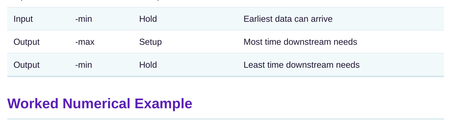
Take an input path. Clock period is 8.00 ns. Max input delay is 3.20 ns. The internal path from the input port to the capture flip-flop takes 4.05 ns. The capture flip-flop needs 0.15 ns of setup time. There is 0.20 ns of clock uncertainty.
# Worked input setup slack
Capture edge (period)        = 8.00 ns
Minus input delay (max)      = -3.20 ns
Minus setup time             = -0.15 ns
Minus uncertainty            = -0.20 ns
Required time at port        =  4.45 ns
Internal arrival             =  4.05 ns
Setup slack = 4.45 - 4.05    = +0.40 ns   -> PASS
Now an output path. Period 8.00 ns. Max output delay 2.60 ns. Internal launch-to-port delay is 5.10 ns. Uncertainty 0.20 ns.
# Worked output setup slack
Capture edge (period)        = 8.00 ns
Minus output delay (max)     = -2.60 ns
Minus uncertainty            = -0.20 ns
Required time at port        =  5.20 ns
Internal arrival at port     =  5.10 ns
Setup slack = 5.20 - 5.10    = +0.10 ns   -> PASS (tight)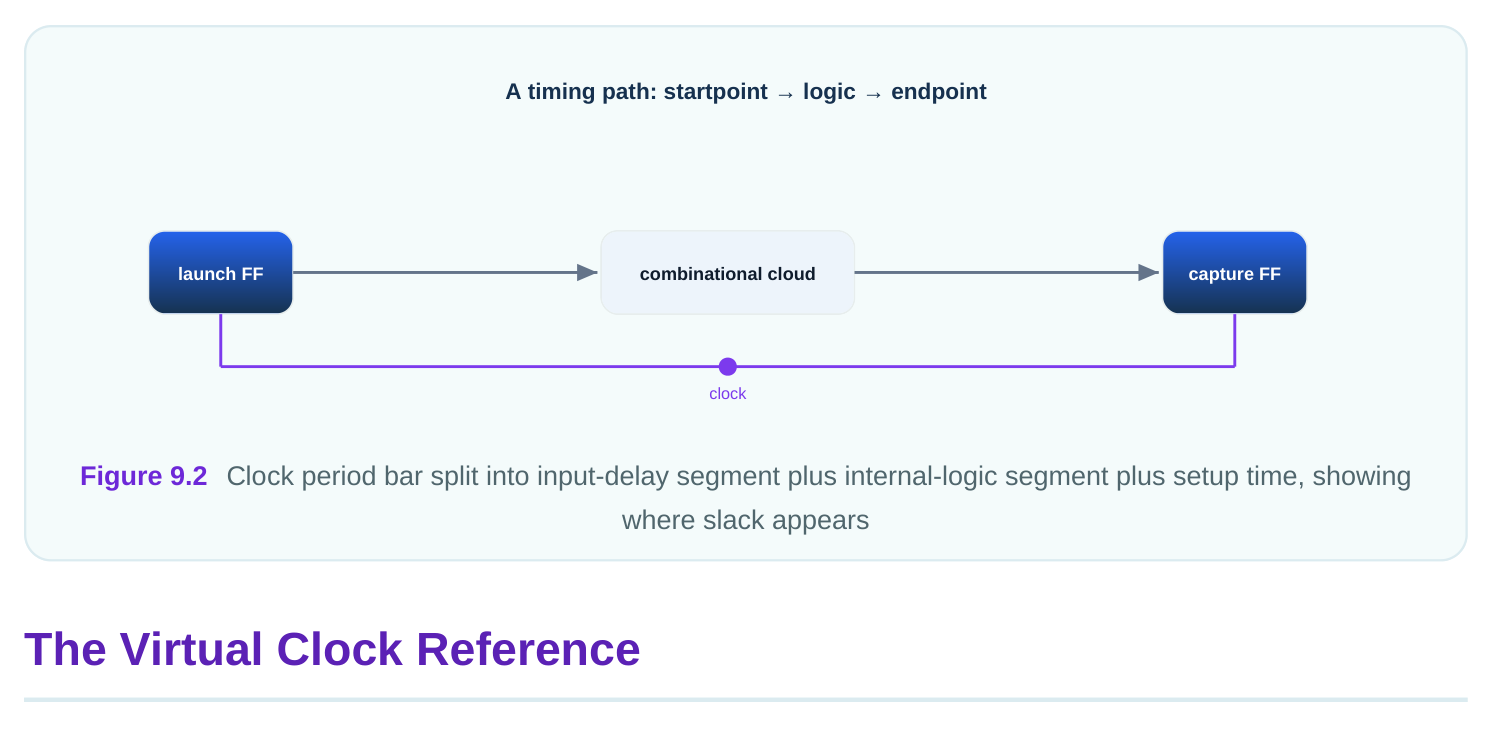
Sometimes the clock that launches an external signal is not a clock that exists inside our chip at all. It only lives outside. We still need something to reference the input or output delay against. The answer is a virtual clock: a clock defined with no source port, existing only as a timing reference. You create one with create_clock but without giving it a port. It has a period and edges like any clock, but it drives no real pin. You then point your input and output delays at it. This cleanly models the case where the off-chip device runs on its own clock that our chip never sees.
# standard SDC — portable across compliant tools
# Virtual clock: a reference with no physical port
create_clock -name virt_clk -period 8.00
# Boundary delays referenced to the virtual clock
set_input_delay  -clock virt_clk -max 3.20 [get_ports data_in]
set_output_delay -clock virt_clk -max 2.60 [get_ports data_out]
To inspect what the tool computed for a boundary path, a report command helps. Flags vary.
of a path against a clock. Input delay is the time from the external launch edge until data reaches our input port, say 3.20 ns. Output delay is the time the downstream chip needs the data before its capture edge, say 2.60 ns. Together they let the tool finish boundary checks.
consumes part of the period; the rest is for internal logic. With an 8.00 ns period and 3.20 ns input delay, internal logic gets at most 4.80 ns minus setup time. With a 2.60 ns output delay, internal logic must finish within 5.40 ns at the port.
it is the worst late case; the min value drives hold because it is the worst early case. For an input, max 3.20 ns is the latest arrival and threatens setup; -min 1.10 ns is the earliest and threatens hold.
period is available inside the chip. That is far too optimistic. The boundary path shows large positive slack but can silently fail in the real system, because the off-chip time was never counted.
the setup slack (ignore uncertainty)? Required time is 8.00 - 3.20 - 0.15 = 4.65 ns. Arrival is 4.05 ns. Slack is 4.65 - 4.05 = +0.60 ns. The path passes comfortably.
no physical port; it exists only as a reference. You use it when the clock launching or capturing an external signal lives off-chip and never enters your design, so input and output delays still have a clean edge to reference.
Key Takeaways
- set_input_delay models how late off-chip data arrives; set_output_delay models how early the downstream chip needs data.
- Both describe off-chip timing against a clock edge, splitting the period between outside and inside the chip.
- The -max value feeds setup (worst late case) and the -min value feeds hold (worst early case).
- An unconstrained boundary port is assumed to have the whole period inside, which is dangerously optimistic.
- A virtual clock is a reference-only clock with no port, used when the launching or capturing clock is purely off-chip.
Comments
Leave a Reply