 ChipBuddy
← Home
ChipBuddy
← Home
Virtual Clocks & I/O Timing Budgets
Virtual Clocks and I/O Timing Budgets
A chip does not live alone. It sits on a board next to other chips. Data flows in through input ports and out through output ports. To time those data paths, the timing tool needs to know when data arrives and when it is needed, relative to a clock. But sometimes the clock that controls the outside device is not present inside your chip at all. That is where a virtual clock comes in. This chapter explains virtual clocks, why a clock with no port is useful, and how to split the period budget between the chip and the board. A virtual clock is a clock that exists only in the constraint file. It has a period and a waveform like any other clock, but it is not attached to any port or pin on your chip. It represents a clock that lives outside, on another chip or on the board. We use it as a reference point for input and output timing. The data on a port is timed relative to this outside clock, not to any internal clock. In SDC (the timing constraint format), you create a virtual clock with the same create_clock command, but you give it no port. You name it, give it a period, and stop. Then your input and output delay constraints point at that virtual clock as their reference. This lets you model the timing of the board even though the board's clock is invisible inside your design.
Why a Clock With No Port Is Useful
It seems odd to define a clock that connects to nothing. The reason is that I/O timing is always relative to some clock. An input delay says how late data arrives after a clock edge. An output delay says how
much time the outside world needs after a clock edge. That clock is often a board clock that never enters your chip as a usable timing source. Consider a chip that receives data from a neighbor. The neighbor launches the data on its own clock. Your chip captures it on your internal clock. If both run from the same board oscillator, the launching clock is real but it may not have a clean internal copy you can reference. A virtual clock stands in for the neighbor's launching clock, so you can express when the data leaves the neighbor.
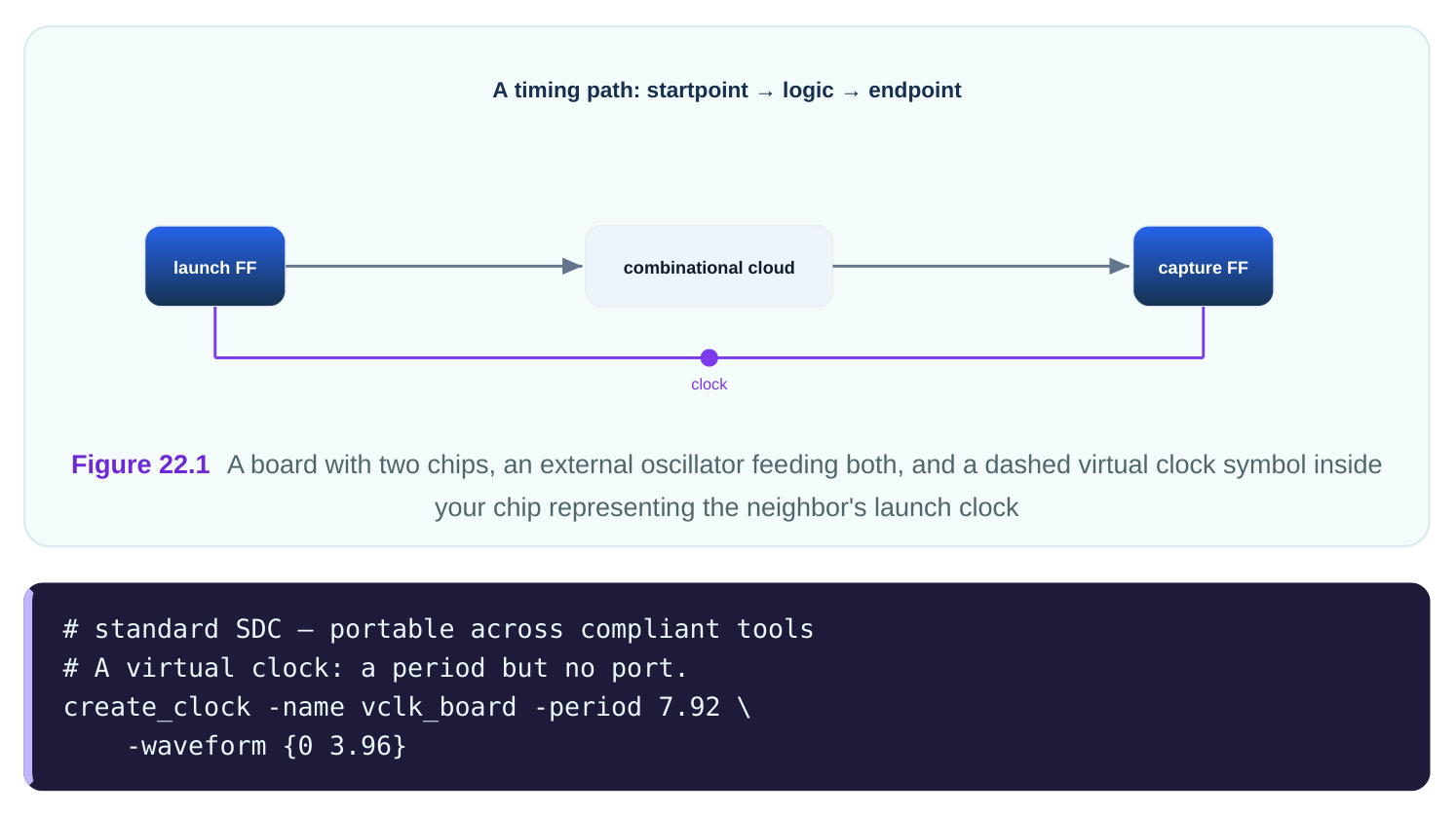
Notice there is no get_ports at the end. That absence is what makes it virtual. The tool now has a 7.92 ns reference it can use for I/O delays, even though no wire inside the chip carries it.
| Clock type | Has a port? | Used for | Example period (ns) |
|---|---|---|---|
| Real input clock | Yes | Internal registers | 4.50 |
| Generated clock | Source pin | Derived domains | varies |
| Virtual clock | No | I/O reference only | 7.92 |
Splitting the Period Budget
The total period is a fixed budget shared between your chip and the outside world. For an input, the budget covers two things: the time the data spent outside getting to your port, and the time it has inside to reach a register. For an output, the budget covers the time inside to leave your port, plus the time the outside device needs after that. Imagine a virtual clock with a 7.92 ns period. Data launches outside on its rising edge. It takes some time to travel through the neighbor's logic and across the board to your input port. That outside time is
the input delay. Whatever is left of the 7.92 ns is your internal budget to capture the data. If the input delay is 5.18 ns, your chip has only 7.92 − 5.18 = 2.74 ns to get the data to a register.
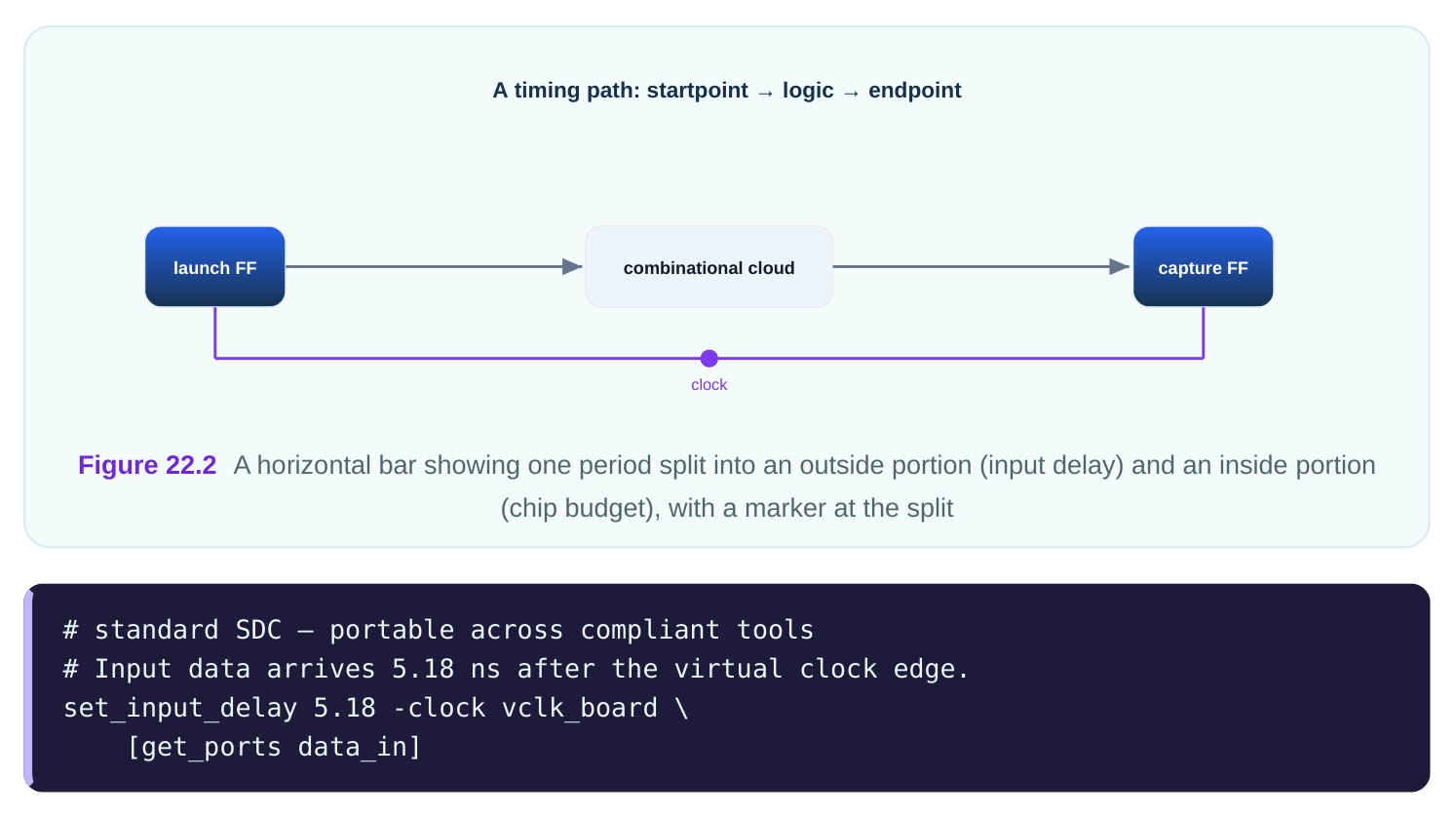
The output works the same way in reverse. The output delay is the time the outside device needs after your chip drives the port. If the virtual clock is 7.92 ns and the downstream device needs 4.36 ns of setup and board travel, your chip must have the data out by 7.92 − 4.36 = 3.56 ns. You write that with
set_output_delay .
# standard SDC — portable across compliant tools
# Downstream needs 4.36 ns after the virtual clock edge.
set_output_delay 4.36 -clock vclk_board \
[get_ports data_out]| Budget piece | Symbol in SDC | Example value (ns) | Whose time |
|---|---|---|---|
| Period | create_clock -period | 7.92 | shared |
| Input delay | set_input_delay | 5.18 | outside |
| Chip input budget | leftover | 2.74 | your chip |
| Output delay | set_output_delay | 4.36 | outside |
| Chip output budget | leftover | 3.56 | your chip |
Referencing I/O Delays to a Virtual Clock
The whole point of the virtual clock is to be the reference for these delays. Every set_input_delay and set_output_delay names a clock with -clock . When that named clock is the virtual one, the
tool measures the delay from the virtual clock's edge. This keeps the chip's internal clock separate from the I/O reference, which is often what you want. Why separate them? If your internal capture clock and the external launch clock are the same physical oscillator but have different on-chip delays, using the internal clock as the I/O reference would mix in your own clock tree delay. The virtual clock gives a clean, delay-free reference for the outside world, while your internal clock carries its real on-chip latency. Here is a worked example tying it together. The virtual clock vclk_board is 7.92 ns. Input data has an input delay of 5.18 ns. Inside, the data must reach a register clocked by your real internal clock. The tool launches the data at the virtual clock's edge plus 5.18 ns, then captures it at the internal clock's next edge. The setup check compares the two. If the internal logic plus clock tree leaves less than 2.74 ns, the path fails.
# illustrative — names vary by tool
# Report the input path referenced to the virtual clock.
report_timing -from [get_ports data_in] \
-to [get_pins capture_ff/D] -input_delay
A common practice is to use a different launch and capture relationship for the two ends. The input uses the virtual clock as the launch reference. The capture uses your internal clock. Because they may be the same period but different waveforms or latencies, the tool aligns them just like any two-clock crossing. Getting the virtual clock's period and waveform right is therefore essential; a wrong virtual period throws off every I/O budget at once. The biggest mistake with virtual clocks is forgetting to define one and instead referencing I/O delays to an internal clock that carries on-chip tree delay. That double-counts the clock tree and makes the I/O analysis pessimistic or wrong. The second mistake is giving the virtual clock a period that does not match the real board clock, which corrupts every input and output budget tied to it.
Interview Q&A
exists only in the constraint file and represents a clock outside your chip, on the board or a neighbor. It serves as the reference for input and output delays.
clock, and the controlling clock often lives outside your chip. The virtual clock stands in for that external clock so you can express when data leaves or is needed. It gives a clean, delay-free reference.
delay) plus your chip's internal budget. With a 7.92 ns virtual clock and a 5.18 ns input delay, your chip has 7.92 − 5.18 = 2.74 ns to reach a register. The two pieces must fit inside the period.
naming the virtual clock. The tool then measures the delay from the virtual clock's edge. For example,
set_input_delay 5.18 -clock vclk_board on the data port.clock tree delay. Using it as the I/O reference would mix that delay into the external budget and double-count it. A virtual clock gives a delay-free reference for the outside world.
to it is corrupted at once, because all the leftover chip budgets are computed from that period. A wrong period makes the I/O analysis optimistic or pessimistic across the whole interface.
Key Takeaways
- A virtual clock has a period and waveform but no port; it models a clock that lives outside your chip.
- I/O timing is always relative to a clock, so a clock with no port gives a clean reference for input and output delays.
- The period is a shared budget: input delay plus chip budget, or chip budget plus output delay, must fit inside it.
- Reference
set_input_delayandset_output_delayto the virtual clock with-clockto keep on- chip tree delay out of the I/O budget. - A wrong virtual-clock period corrupts every I/O budget at once, so match it to the real board clock.
Comments
Leave a Reply