 ChipBuddy
← Home
ChipBuddy
← Home
Defining Clocks
Why Every Synchronous Check Needs a Clock
A clock is the heartbeat of a synchronous chip. A synchronous design (one where flip-flops update on clock edges) does nothing useful until the clock is defined. The clock sets the deadline for every register-to-register path. The timing tool cannot check timing without a clock. With no clock, there is no period, so there is no required time, so there is no slack. The tool simply skips those paths. They look fine because nothing is measured. This is why declaring clocks is the first real step in any SDC file. Before input delays, before exceptions, before anything, you tell the tool which wires are clocks and how fast they tick. Everything else hangs off that.
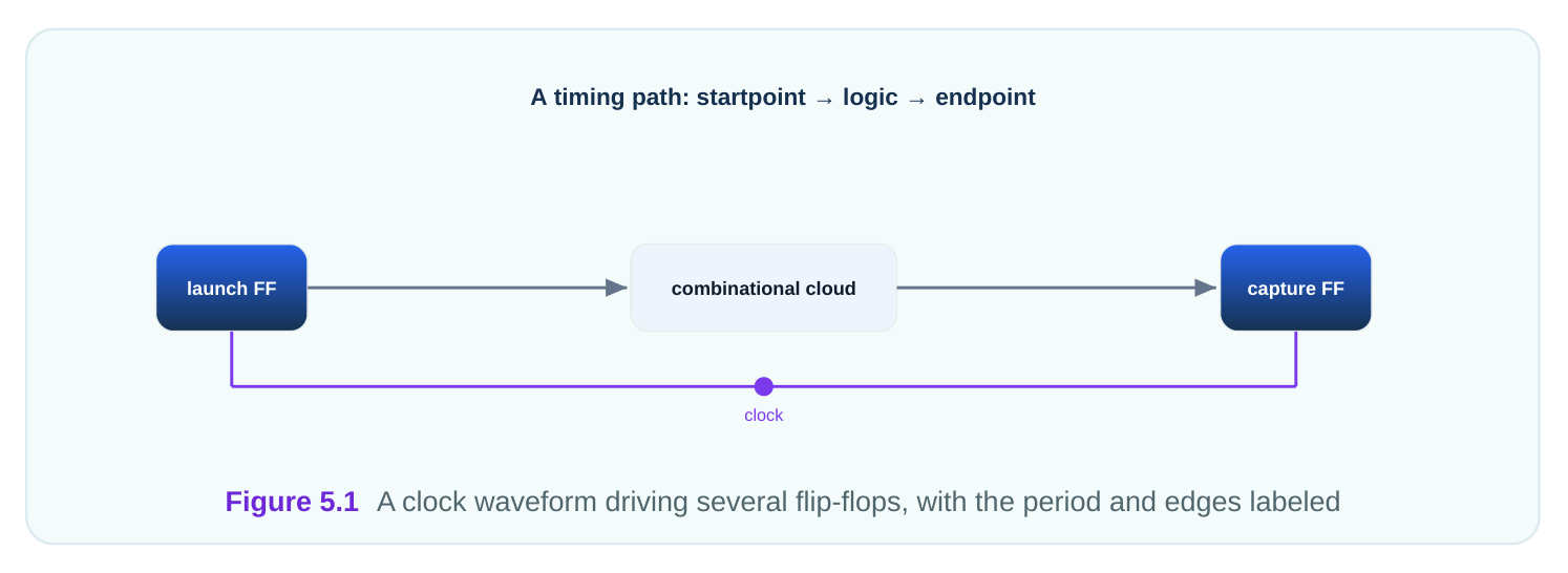
A clock declaration does three things. It names a signal as a clock. It sets the period. And it describes the waveform, the shape of the rising and falling edges within one period. From these, the tool builds every timing check.
Defining a Primary Clock
A primary clock is a clock that enters the chip from outside, usually at an input port. You define it with
create_clock . This is the most common and most important constraint in the whole file.The command needs three things: a name, a period, and a source. The name lets you refer to the clock later. The period sets the cycle time. The source is the port or pin where the clock arrives.
# standard SDC — portable across compliant tools
# A primary clock entering at port clk_in
create_clock -name sys_clk -period 4.0 [get_ports clk_in]
This says: there is a clock called sys_clk, its period is 4.0 ns, and it arrives at port clk_in. A 4.0 ns period means 250 million cycles per second, or 250 MHz. The tool now knows the deadline for every path this clock captures. Always give a clock an explicit name with -name . Without a name, the clock takes the port's name, which can confuse later commands. A clear name like sys_clk or core_clk makes the rest of the file readable.
| Argument | Purpose | Example |
|---|---|---|
| -name | Names the clock object | -name sys_clk |
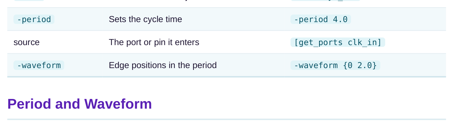
The period is the full length of one clock cycle. A period of 4.0 ns means each cycle lasts 4.0 ns. Inside that cycle, the clock rises once and falls once. The waveform says exactly when. The waveform is a pair of numbers: the rising edge time and the falling edge time, both within one period. The default waveform for a 4.0 ns clock is {0 2.0} . The clock rises at 0 ns and falls at 2.0 ns, giving a 50 percent duty cycle (the fraction of the period the clock is high).
# standard SDC — portable across compliant tools
# Default 50 percent duty cycle: rise at 0, fall at half the period
create_clock -name sys_clk -period 4.0 -waveform {0 2.0} [get_ports clk_in]
You can shift the duty cycle when the hardware needs it. If a clock must be high for only 1.5 ns of a 4.0 ns period, you write the falling edge at 1.5 ns. The duty cycle is then 37.5 percent, not 50.
# worked example — duty cycle from a waveform
Period:                 4.0 ns
Waveform:               {0 1.5}   (rise at 0.0, fall at 1.5)
High time = 1.5 - 0.0 = 1.5 ns
Low time  = 4.0 - 1.5 = 2.5 ns
Duty cycle = 1.5 / 4.0 = 37.5 percent
A non-50-percent duty cycle matters for logic that uses both edges. If a path is triggered on the falling edge, its timing shifts when the duty cycle changes. Getting the waveform right keeps those checks honest.
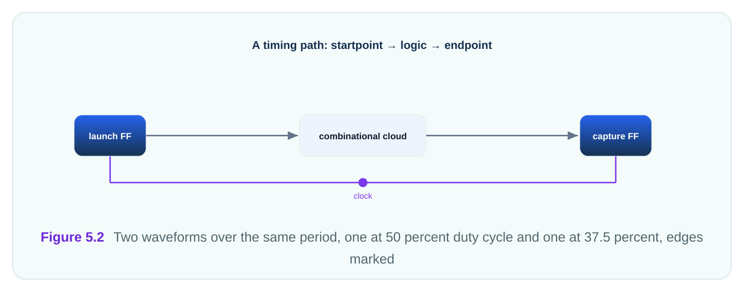
| Waveform | Period | High time | Duty cycle |
|---|---|---|---|
| {0 2.0} | 4.0 ns | 2.0 ns | 50 percent |
The source is the object where the clock is defined. For a primary clock it is usually an input port, the pin where the clock enters the chip. The tool starts measuring clock arrival from this point.
You can also define a clock on an internal pin, not just a boundary port. This is useful when a clock is generated or gated inside the chip and there is no dedicated input port for it. The command is the same; only the source object changes. The source choice affects clock latency (the delay from the clock source to each flip-flop). Latency is measured from the source you name. If you define the clock too far downstream, you lose visibility into the delay before that point.
# standard SDC — portable across compliant tools
# Define a clock on an internal pin instead of a boundary port
create_clock -name gen_clk -period 5.0 [get_pins clk_gen/clk_out]
Pick the source where the clock truly originates from the tool's point of view. For most designs that is the boundary input port. The cleaner the source, the more accurate every downstream latency and skew number becomes.
Virtual Clocks
A virtual clock is a clock with no source pin. It exists only as a timing reference. You create it by leaving out the source object in create_clock . It paces nothing inside the chip, but it anchors interface timing. Why have a clock that drives nothing? Because the chip's inputs and outputs are timed against an external clock that may not physically enter your block. The virtual clock represents that outside clock so you can write input and output delays against it.
# standard SDC — portable across compliant tools
# A virtual clock: named, has a period, but no source object
create_clock -name vclk -period 4.0
set_input_delay  -clock vclk 1.40 [get_ports async_in]
set_output_delay -clock vclk 1.10 [get_ports async_out]
Here vclk has a 4.0 ns period but no port. The input and output delays on the boundary ports are measured relative to vclk's edges. This lets you time the interface even when the external clock never appears inside your design. Virtual clocks are common at block boundaries and for interfaces to other chips. They keep interface timing well-defined without inventing a fake physical signal. Used well, they make boundary constraints clean and accurate.
| Clock kind | Has a source pin? | Paces internal logic? | Main use |
|---|---|---|---|
| Primary | Yes | Yes | Main on-chip clock |
| Virtual | No | No | Reference for interface timing |
Interview Q&A
which sets the required time, which sets the slack. With no clock there is no deadline, so the tool skips those paths entirely. They look fine only because nothing is being measured.
you reference the clock later, the period sets the cycle time, and the source is the port or pin where the clock enters. For example, sys_clk with a 4.0 ns period at port clk_in runs at 250 MHz.
like {0 2.0} . The duty cycle is the fraction of the period the clock is high. A {0 1.5} waveform on a 4.0 ns clock gives a 37.5 percent duty cycle.
edge sits. A {0 1.5} waveform shifts the falling edge to 1.5 ns instead of 2.0 ns, changing the timing of falling-edge paths. Getting the waveform right keeps those checks honest.
source pin, so it paces nothing. You use it to represent an external clock that does not physically enter your block, so you can write input and output delays against it. It keeps interface timing well-defined without a fake signal.
name, which can confuse later commands that reference the clock. A clear name like sys_clk or core_clk keeps the whole file readable and avoids ambiguity.
Key Takeaways
- A clock is the heartbeat of a synchronous design; without it, the tool skips timing checks and they falsely look clean.
- Use create_clock with a name, period, and source to define a primary clock that enters the chip.
- The waveform sets the duty cycle; a
{0 1.5}waveform on a 4.0 ns clock means 37.5 percent high time. - The source defines where latency is measured from, so pick where the clock truly originates.
- A virtual clock has no source and serves only as a reference for input and output interface timing.
Comments
Leave a Reply