 ChipBuddy
← Home
ChipBuddy
← Home
Completing Port Constraints — Drive, Load & Transition
Completing Port Constraints — Drive, Load & Transition
Input and output delays tell the tool when signals cross the chip boundary. But timing is not only about when. It is also about signal shape. A real signal does not switch instantly; it ramps from low to high over some time. That ramp time is the transition or slew. Slow slews make gates slower and can break the design. At the chip boundary, the tool has no idea what is driving an input or what an output is feeding. So it cannot know the slew at an input, or the delay added by the load on an output. The SDC constraint format fixes this with drive and load constraints, plus a set of design-rule limits that keep slews, capacitance, and fanout in check. This chapter covers all of them and shows why a bare port gives wrong answers. A gate is a small logic element. Capacitance is the electrical load a gate must charge to switch its output. Fanout is how many gate inputs a single output drives. All three influence delay. The reason these constraints matter so much is that gate delay is not a fixed property. The same gate is fast when it drives a sharp input edge and a light load, and slow when it drives a lazy edge and a heavy load. Delay is a function of input slew and output load. So if the tool guesses the slew and load at the chip boundary, it guesses the delay of every gate near that boundary. Drive and load constraints
replace those guesses with realistic values, and the design-rule constraints stop slews and loads from drifting into unsafe territory anywhere in the design.
Why a Bare Port Gives Wrong Slews
When you leave an input port with no drive information, the tool assumes a perfect, infinitely strong driver. The slew at the port becomes ideal, near zero. That is unrealistic. A real upstream gate is finite, so the real slew might be 0.40 ns, not 0.00 ns. A faster-than-real slew makes the first gate inside look faster than it is, so the tool underestimates delay. The opposite mistake happens at outputs. With no load, the tool assumes the output drives nothing. The final gate looks artificially fast, because driving zero capacitance takes almost no time. In reality the output may drive 0.030 pF of board and pin capacitance, which adds real delay. Both errors are optimistic, and optimism is dangerous. The chip looks like it meets timing in the tool but fails on the bench. Setting drive and load makes the boundary realistic.
| Bare port assumption | Reality | Effect on timing |
|---|---|---|
| Input: infinite drive, ~0 slew | Finite driver, 0.40 ns slew | First gate too fast (optimistic) |
| Output: zero load | 0.030 pF real load | Last gate too fast (optimistic) |
| No transition limit | Slews can grow unchecked | Hidden slow paths |
Setting Input Drive
There are two ways to model what drives an input. The simple way is set_drive , which gives a fixed drive resistance. The better, more realistic way is set_driving_cell , which tells the tool to behave as if a named library gate is driving the port. The tool then computes the slew from that gate's real characteristics and the load it sees.
set_driving_cell is preferred because slew depends on the load. A real driving gate producesdifferent slews for different loads, and the tool models that automatically. You name a library cell and, optionally, its input pin and the input slew feeding it.
# standard SDC — portable across compliant tools
# Model an input as if driven by a real library gate
set_driving_cell -lib_cell BUFX4 -pin Z [get_ports data_in]
# Simpler alternative: a fixed drive resistance (less accurate)
set_drive 18.5 [get_ports addr_in]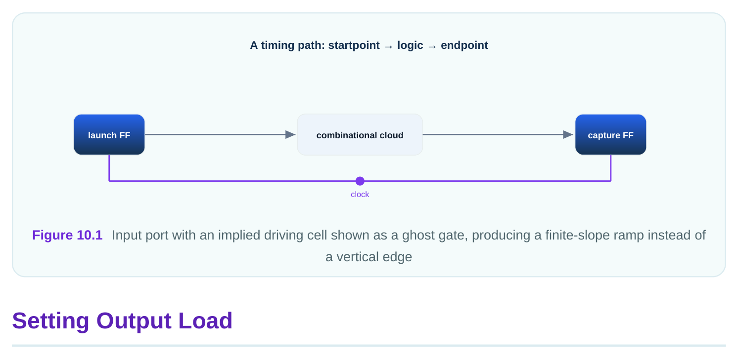
set_load tells the tool the capacitance an output port drives. This is the board trace, the package pin,and the input capacitance of the next chip, all summed. A realistic value might be 0.030 pF for a normal pin, or higher for a heavily loaded bus. The load directly changes the delay of the last gate inside the chip. More load means more time to charge, so more delay. Getting this number right is essential for honest output timing. You can also apply set_load to internal nets, but at the boundary it is mandatory.
# standard SDC — portable across compliant tools
# External capacitance seen by the output port
set_load 0.030 [get_ports data_out]
# A more heavily loaded output bus
set_load 0.085 [get_ports {bus_out[0] bus_out[1] bus_out[2]}]| Output situation | Typical load | Reason |
|---|---|---|
| Single downstream input | 0.015–0.030 pF | One pin plus short trace |
| Shared bus, several loads | 0.060–0.120 pF | Multiple pins and longer trace |
| Test or probe point | up to 0.200 pF | Extra probe capacitance |
Design-Rule Constraints: Transition, Capacitance, Fanout
Beyond boundary modeling, the tool enforces health limits on every net, called design-rule constraints. They are not about meeting the clock; they are about keeping signals clean. Three matter most.
set_max_transition caps the slew on a net. A slow slew wastes time and burns power, and veryslow slews can cause logic to misbehave. A typical cap is 0.35 ns. set_max_capacitance caps how
much load a gate may drive, for example 0.150 pF, so no gate is overloaded. set_max_fanout caps how many inputs one output feeds, for example 24, so signals stay strong. These are limits, not targets. The tool inserts buffers or upsizes gates to satisfy them. They protect against electrical problems that pure path timing would miss. It is worth seeing why a slew limit matters even when a path meets the clock. A very slow edge spends a long time in the region between fully low and fully high. During that time the gate draws extra current and is more vulnerable to noise from neighboring wires. A slow edge can also stretch the delay of the next gate in unpredictable ways, because that gate sees a sluggish input. So a net can have perfectly fine path slack and still be a problem if its slew is out of bounds. The transition limit catches exactly this. Capacitance and fanout limits work the same way: they keep each driver within the load it was designed to handle, so the library's delay numbers stay trustworthy.
# standard SDC — portable across compliant tools
# Cap slew, capacitance, and fanout across the design
set_max_transition 0.35 [current_design]
set_max_capacitance 0.150 [current_design]
set_max_fanout 24 [current_design]| Constraint | Limits | Typical value | If violated |
|---|---|---|---|
| set_max_transition | Net slew | 0.35 ns | Slow, noisy edges |
| set_max_capacitance | Load on a gate | 0.150 pF | Overloaded driver |
| set_max_fanout | Inputs per output | 24 | Weak, slow signal |
A Realistic Environment and Worked Example
A complete boundary environment names a driving cell on each input, a load on each output, and design-rule caps across the design. This is sometimes called modeling the environment. Skipping any piece leaves a hole that lets optimistic timing through. Here is a small worked example of how load changes output delay. Suppose the last gate's delay rises by 4.0 ns per pF of load (its drive strength). With no load set, the tool sees 0.000 pF, so added delay is 0.000 ns. With a real load of 0.030 pF, added delay is 4.0 × 0.030 = 0.120 ns.
# Worked load-to-delay example
Drive sensitivity   = 4.0 ns per pF
Bare port load      = 0.000 pF -> 0.000 ns added (optimistic)
Real load           = 0.030 pF -> 0.120 ns added (honest)
Hidden error if bare = 0.120 ns of optimism on this path
Now slew. Suppose a driving cell produces a 0.40 ns slew at the port, and the first gate adds 0.5 ns of delay per ns of input slew. A bare port assumes ~0.00 ns slew, hiding 0.5 × 0.40 = 0.20 ns.
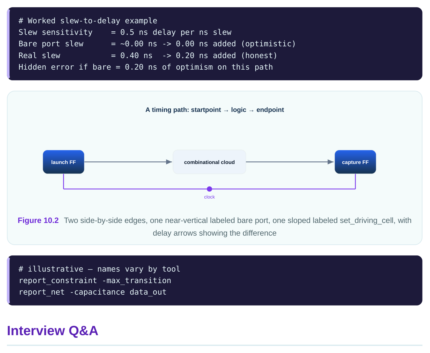
so the slew is near 0.00 ns. A real driver gives a finite slew like 0.40 ns. The near-zero slew makes the first internal gate look faster than reality, so the tool underestimates delay. It is an optimistic error.
resistance and ignores how slew changes with load. set_driving_cell models a real library gate, so the slew is computed from that gate plus the actual load. set_driving_cell is more accurate and preferred for boundary modeling.
internal gate must charge. More load means more delay. With no load the tool assumes 0.000 pF and reports the gate as artificially fast. A real 0.030 pF load might add 0.120 ns, which the bare port hides.
health, not clock timing: set_max_transition limits slew (e.g. 0.35 ns), set_max_capacitance limits load on a gate (e.g. 0.150 pF), set_max_fanout limits inputs per output (e.g. 24). They protect against electrical problems that path timing alone would not catch.
bare port? A bare port assumes 0.000 pF, so it adds 0.000 ns. The real load adds 4.0 × 0.030 = 0.120 ns. The bare port hides 0.120 ns of optimism on that output path.
worst acceptable value, not a goal. The tool fixes any net that exceeds them by buffering or upsizing. They exist to keep edges clean and gates within safe load, preventing electrical failures that timing slack would not reveal.
Key Takeaways
- A bare port assumes infinite input drive and zero output load, both optimistic and dangerous.
- set_driving_cell models a real gate so slew tracks load; it is preferred over a fixed set_drive.
- set_load gives the output's real capacitance, often 0.030 pF, and directly adds delay to the last gate.
- Design-rule constraints (transition, capacitance, fanout) cap signal health, not clock timing, and the tool buffers to meet them.
- A complete environment names drivers, loads, and limits on every boundary, closing the holes that let optimistic timing slip through.
Comments
Leave a Reply