 ChipBuddy
← Home
ChipBuddy
← Home
Source-Synchronous Interfaces
Source-Synchronous Interfaces
Most timing assumes the sender and the receiver share one clock. But many fast interfaces do not. Instead, the sender ships a clock right alongside the data, on its own wire. The receiver uses that traveling clock to capture the data. This is a source-synchronous interface. This chapter explains how it works, how to constrain it with input and output delays in SDC (the timing constraint format), and why it differs from a common-clock scheme. In a source-synchronous interface, the chip that sends the data also sends the clock that goes with it. The data and the clock travel together, side by side, across the board. Because they share the same path, they pick up nearly the same delay. So when the data arrives, the clock arrives at almost the same moment. The receiver does not need its own copy of the sender's clock; it uses the one that came with the data. This is very different from a system-synchronous, or common-clock, interface. There, one board clock fans out to both chips, and the data is timed against that shared clock. The trouble with a common clock is that the data wire and the clock wire take different paths, so their delays differ. Sourcesynchronous solves that by making data and clock share the trip. This chapter shows the two main flavors, edge-aligned and center-aligned, and how to express each.
Clock Sent Alongside Data
Picture a sender driving eight data bits and one clock onto nine wires that run together across the board. The sender launches all of them from the same internal clock edge. They travel together. At the receiver, all nine arrive after roughly the same board delay. The receiver uses the arriving clock to latch the eight data bits. Because the clock rode along with the data, board delay almost cancels out. If the board adds 1.74 ns of delay to the data, it adds about 1.74 ns to the clock too. The receiver sees both shifted by the same amount, so the relationship between them is preserved. That is the magic of source-synchronous timing: long board delays do not eat the budget the way they do with a common clock.
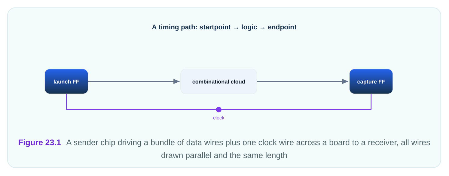
For the timing tool, the key fact is what the sender did before launch. Did it line the clock edge up with the data edge, or did it place the clock edge in the middle of the data window? That choice defines the two flavors and changes the input delay numbers you write.
| Feature | Source-synchronous | Common-clock |
|---|---|---|
| Clock travels with data? | Yes | No |
In an edge-aligned interface, the sender lines up the clock edge with the data transition. The clock edge and the data change happen at the same time. This is common when the sender simply forwards its launch clock. The receiver then has to delay the clock itself, usually by a quarter period, to move the sampling point into the stable middle of the data.
In a center-aligned interface, the sender does the shifting. It places the clock edge in the center of the data valid window. The data is stable on both sides of the clock edge, so the receiver can sample directly without shifting the clock. Center-aligned is friendlier to the receiver because the setup and hold margins are built in by the sender.
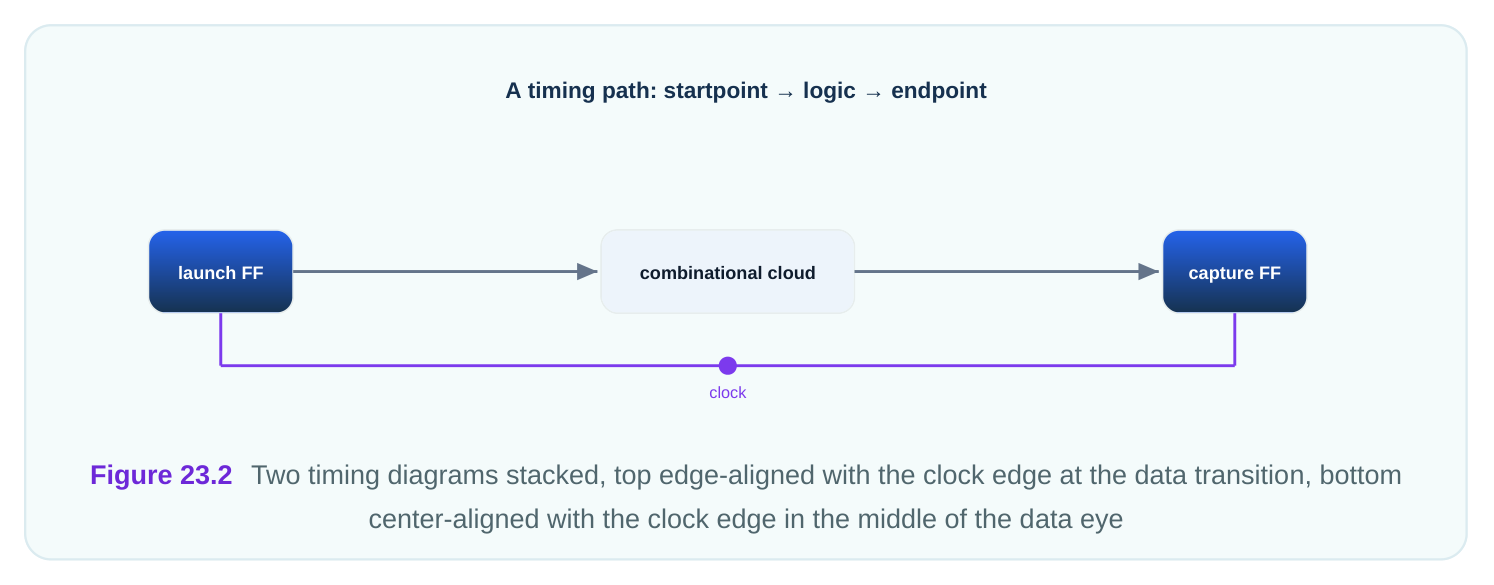
The data valid window, often called the eye, is the time the data stays stable and can be safely sampled. In center-aligned, the clock edge sits in the middle of the eye, so there is margin before (setup) and after (hold). In edge-aligned, the clock edge sits at the edge of the eye, so the receiver must create the margin.
| Flavor | Clock edge sits at | Who creates sampling margin | Typical capture |
|---|---|---|---|
| Edge-aligned | Data transition | Receiver (delays clock) | Shift clock ~quarter period |
| Center-aligned | Middle of data eye | Sender | Sample directly |
A worked example. The interface runs on a 3.60 ns period forwarded clock. In a center-aligned setup, the data eye is 3.60 ns wide and the clock sits in the middle. The setup margin before the clock edge is about half the eye minus skew, and the hold margin after it is similar. If the data-to-clock skew across the bus is 0.47 ns, the usable margin on each side shrinks by that much, leaving roughly 1.33 ns of setup margin on each side of the edge.
Constraining With Input and Output Delays
You constrain a source-synchronous input by describing when the data arrives relative to the forwarded clock. You first create a clock for the forwarded clock at its input port, then set input delays on the data ports referenced to that clock. The input delay captures the skew between the data and the clock, which is what the receiver actually has to deal with. For center-aligned data, the clock edge is in the middle of the eye, so the data arrives a little before the clock (setup side) and stays a little after (hold side). You express this with a maximum input delay
for the late-arriving data and a minimum input delay for the early-arriving data. The gap between max and min input delay equals the part of the eye consumed by skew.
# standard SDC — portable across compliant tools
# Forwarded clock arrives on its own port.
create_clock -name clk_fwd -period 3.60 \
-waveform {0 1.80} [get_ports clk_fwd_in]
# Center-aligned data: max and min input delay around the edge.
set_input_delay -clock clk_fwd -max 0.62 [get_ports rx_data*]
set_input_delay -clock clk_fwd -min -0.55 [get_ports rx_data*]
The max input delay (0.62 ns) marks the latest the data can arrive after the clock edge. The min input delay (−0.55 ns) marks the earliest, before the edge. Together they describe the valid window the receiver sees. The tool then checks that the receiver's internal capture path fits inside this window. For the output side, where your chip is the sender, you describe how your data lines up with the clock you forward. You use set_output_delay referenced to the forwarded clock. For a center-aligned output, you set max and min output delays so the data eye is centered on the clock you drive out.
# standard SDC — portable across compliant tools
# Your chip forwards a clock and centers data on it.
set_output_delay -clock clk_fwd -max 0.71 [get_ports tx_data*]
set_output_delay -clock clk_fwd -min -0.48 [get_ports tx_data*]
For an edge-aligned interface, the numbers shift because the clock edge is at the data transition, not the center. The input delay values then cluster near zero skew, and the receiver's quarter-period clock shift is modeled separately, often as added clock latency on the forwarded clock. The exact split depends on where you account for the quarter-period delay.
Why This Differs From a Common Clock
With a common clock, the data and clock travel separate paths from one shared source. Their board delays differ, and that difference eats directly into the timing budget. If the data wire is 1.20 ns slower than the clock wire, you lose 1.20 ns of margin, and there is little you can do about it at high speed. Source-synchronous removes that penalty because data and clock share the trip. The board delay shifts both equally and cancels in the relationship the receiver cares about. This is why fast buses use source-synchronous: it lets the interface run far above what a common clock could support over the same board. The constraint style differs to match. In a common-clock interface, the input delay is one number relative to the shared clock, modeling the sender's launch plus the data board delay. In sourcesynchronous, you use a max and a min input delay relative to the forwarded clock, modeling the skew window directly. The forwarded clock is the reference, not a board oscillator.
The most common mistake is treating a source-synchronous interface as if it were common-clock. If you reference the data to a board oscillator instead of the forwarded clock, the tool adds the full board delay into the budget and reports failures that do not exist on silicon. Always reference sourcesynchronous data to the clock that travels with it. The second mistake is forgetting the min input delay, which leaves the hold side of the window unchecked and can let a real hold failure slip through.
Interview Q&A
alongside the data on its own wire. The data and clock travel together, so they pick up nearly the same board delay. The receiver captures the data using the arriving clock, not a shared board clock.
feeds both chips, and data and clock take separate paths with different delays. In source-synchronous, data and clock share the trip, so board delay cancels in the relationship that matters. That lets the bus run much faster.
edge at the data transition, so the receiver must shift the clock about a quarter period to sample the stable middle. Center-aligned puts the clock edge in the center of the data eye, so the receiver can sample directly with built-in margin.
describe the data valid window around the forwarded clock edge. Max marks the latest arrival (setup side), min the earliest (hold side). For a 3.60 ns interface you might set max 0.62 ns and min −0.55 ns to capture the skew window.
wires run together and pick up almost the same delay. If the board adds 1.74 ns to the data, it adds about 1.74 ns to the clock too. The receiver sees both shifted equally, so the data-to-clock relationship is preserved.
the data to a board oscillator instead of the forwarded clock. The tool then adds the full board delay into the budget and reports false failures. Always reference the data to the clock that travels with it, and include the min input delay for the hold side.
Key Takeaways
- A source-synchronous interface sends a clock alongside the data, so board delay cancels and the bus can run fast.
- It differs from a common clock, where data and clock take separate paths and their delay difference eats the budget.
- Edge-aligned puts the clock edge at the data transition; center-aligned puts it in the middle of the data eye.
- Constrain source-synchronous data with a max and min input delay referenced to the forwarded clock, describing the skew window.
- The classic error is referencing the data to a board oscillator instead of the forwarded clock, which reports false failures.
Comments
Leave a Reply