 ChipBuddy
← Home
ChipBuddy
← Home
Case Analysis & Mode Configuration
Case Analysis & Mode Configuration (Deep)
A chip often does more than one job. The same gates may run in a "normal" job and a "test" job. The same block may run in a "fast read" mode and a "low power" mode. Each job uses a different path through the logic. Timing analysis must look at one job at a time. If you mix jobs, the timing tool sees paths that never run together. Those paths waste effort and hide real problems. Case analysis is the way you tell the tool which job is active. You set a control pin to a fixed logic value. The tool then treats that pin as a constant. Logic that depends on the other value of that pin goes dark. That logic is "pruned." Pruning means the tool drops paths that can never switch in this job. This chapter explains how to fix pins, how to pick a mode, and how this choice talks to your clocks.
What set_case_analysis Actually Does
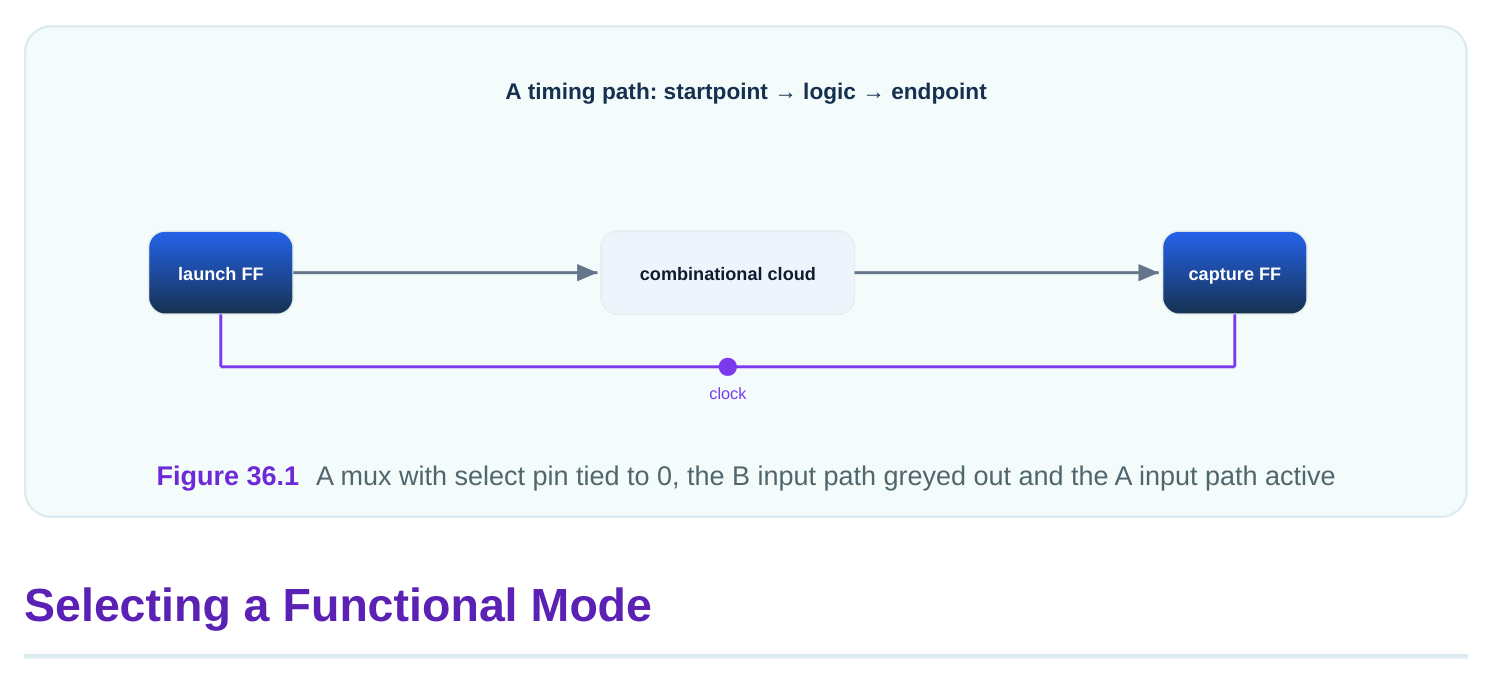
The command set_case_analysis ties a pin or port to a constant. A "port" is a top-level input or output. A "pin" is a connection on a cell inside the design. The constant is 0 or 1 . Once you set it, the tool propagates that value forward. "Propagate" means it pushes the constant through the gates that follow. Here is a small case. Suppose a multiplexer (a "mux") picks between two data sources. A mux has a select pin. If the select is held at 0 , the mux always passes input A. Input B can never reach the output. So every path from input B to the mux output is dead. The tool removes it from analysis.
# standard SDC — portable across compliant tools
set_case_analysis 0 [get_ports test_enable]
set_case_analysis 1 [get_pins mux_sel_reg/Q]
The first line says the test enable port is held low. The second line says one mux select is held high. Both are now constants for this run. Case analysis only changes timing analysis. It does not change the silicon. The gate still exists. You are telling the tool, "for this job, assume this value." If you choose the wrong value, you may hide a path that is actually live. So the value must match the real job.
A "functional mode" is one real operating job of the design. Picture a block with a configuration register. That register selects whether the block runs in "stream mode" or "block mode." The register value drives many muxes and enables across the block. Each mode lights up a different set of paths. You select a mode by setting the configuration pins to the values that mode uses. The table below shows a made-up two-bit mode register.
| Mode name | cfg[1] | cfg[0] | What runs |
|---|---|---|---|
| stream | 0 | 1 | serial datapath, FIFO drain |
| block | 1 | 0 | parallel datapath, burst buffer |
| idle | 0 | 0 | clock gating only, no datapath |
| selftest | 1 | 1 | scan-style checkers |
To analyze stream mode, you fix the register to 0 and 1 :
# standard SDC — portable across compliant tools
set_case_analysis 0 [get_pins cfg_reg[1]/Q]
set_case_analysis 1 [get_pins cfg_reg[0]/Q]
Now the tool only sees the stream datapath. The parallel datapath is pruned. You would write a separate file for block mode with the opposite values. Each mode gets its own constraint file. You never put two modes in one file. If you did, the two sets of constants would conflict, and the tool would warn or pick one. A worked illustration. Say stream mode has a critical path of 3.47 ns and block mode has a critical path of 4.12 ns. If you analyzed both at once without case analysis, the tool might report a 5.83 ns path that crosses from the stream FIFO into the block buffer. That cross path is physically impossible. The 5.83 ns number is a ghost. Case analysis deletes the ghost so you see the true 4.12 ns worst case.
Pruning Dead Logic and Why It Helps
"Dead logic" is logic that cannot switch in the current job. It is dead only for this mode, not forever. Pruning dead logic gives three clear gains. First, runtime drops. Fewer paths means less work for the tool. Second, reports get cleaner. You do not scroll past impossible paths to find real ones. Third, optimization aims better. If the tool tries to fix a ghost path, it may add buffers that help nothing. Pruning stops that waste.
| Without case analysis | With case analysis |
|---|---|
| paths from all modes mixed | only active mode paths |
| ghost cross-mode paths reported | ghost paths removed |
| longer runtime | shorter runtime |
| optimizer may chase dead paths | optimizer targets live paths |
There is a risk. If you set a constant on the wrong pin, you may prune logic that is actually alive. The tool will then report a clean result that is wrong. So review your case settings against the design spec. A common check is to count how many endpoints the tool sees before and after. If the count drops far more than you expect, a case value may be too aggressive.
# illustrative — names vary by tool
report_case_analysis
report_disabled_paths -summary
These reports list every constant you set and every path that went dark. Read them after each run. They are your safety net.
Test Mode Versus Functional Mode
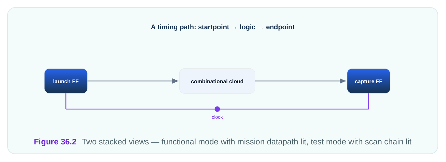
Test mode is a special job. During manufacturing test, the chip runs scan patterns. "Scan" links the flipflops into long shift chains. A "scan enable" pin switches the design from normal operation to shift operation. In normal operation the data goes through real logic. In shift operation the data marches through the chain. These two jobs need opposite case values. In functional mode you hold scan enable at its inactive value. In test mode you may hold it active for the shift part, or release it for the capture part. The table shows a made-up setup.
| Pin | Functional value | Scan-shift value | Scan-capture value |
|---|---|---|---|
| scan_enable | 0 | 1 | 0 |
| test_mode | 0 | 1 | 1 |
| bypass_pll | 0 | 1 | 1 |
In functional mode you also often hold test_mode at 0 . This prunes the whole test wrapper. The test clock logic goes dark. You analyze only the mission logic. In test mode you do the opposite. You hold test_mode at 1 , and now the scan paths become real and the mission datapath may go dark.
# standard SDC — portable across compliant tools
# functional mode setup
set_case_analysis 0 [get_ports scan_enable]
set_case_analysis 0 [get_ports test_mode]
set_case_analysis 0 [get_ports bypass_pll]
A key point. Test timing and functional timing are different runs with different files. You do not try to close both in one pass. The clocks differ. The constants differ. The active paths differ. Keep them apart.
How Case Analysis Interacts With Clocks
Clocks and case analysis are tightly linked. Many designs choose a clock source with a mux. The clock mux has a select pin. If you do not fix that select, the tool may not know which clock reaches the flops. Or it may try to time both clocks onto the same flop. That gives wrong or doubled analysis. So you set the clock mux select with case analysis. This forces one clock through. The other clock stops at the mux. Picture a clock mux that picks between a 920 MHz main clock and a 38 MHz test clock.
# standard SDC — portable across compliant tools
# pick the main clock through the clock mux
set_case_analysis 1 [get_pins clk_mux/S]
create_clock -name main_clk -period 1.087 [get_ports osc_in]
Here select 1 passes the main clock. The period 1.087 ns matches 920 MHz. The test clock never reaches the flops, so the tool does not create a false relationship between the two clocks. Case analysis can also gate clocks off. If you hold a clock gate enable at 0 , the clock past that gate stops. Every flop fed by that branch becomes unclocked for this run. Those flops drop out of analysis. That is correct when the branch truly idles in this mode.
| Clock control | Case value | Effect on timing |
|---|---|---|
| clock mux select | fix to one input | only chosen clock propagates |
| clock gate enable | 0 | downstream clock stops, flops idle |
| clock gate enable | 1 | downstream clock active, flops timed |
| divider reset | hold | divider output frozen, no toggling |
The order matters in practice. Set clock case values before you lean on clock relationships. If the clock mux is unset when clocks are created, the tool may build relationships you must later undo. Fix the clock path first. Then the clocks land where the mode expects. A worked illustration. A design has two clock domains joined by a mux. In main mode you fix the select to pass the 1.087 ns clock. The reported setup slack on a flop is positive 0.214 ns. If you had left the select free, the tool might also time the 38 MHz test clock onto the same flop. The test clock has a huge period, so it would show a falsely large positive slack. That false comfort could hide the real 0.214 ns margin. Fixing the select keeps the report honest.
Interview Q&A
timing analysis. The tool treats that value as a constant. It then drops any path that depends on the other value. This selects one operating job and removes paths that cannot switch in that job.
analysis only tells the timing tool what value to assume for this run. If you assume a wrong value, you can hide a real path, so the value must match the true mode.
values, different clocks, and different active paths. Mixing them creates conflicting constants and ghost paths. Separate files give one clean job per run, so reports and optimization stay correct.
a fixed select, the tool may not know which clock reaches the flops, or may time both. Setting the select with case analysis forces one clock through and stops the others at the mux.
that is actually live. The tool then reports a clean but wrong result. Check the endpoint count and the disabled-path report after each run to catch this.
two modes that never run together. It shows a timing number for something that cannot happen. Case analysis fixes the mode selectors so the cross-mode connection is broken and the ghost path disappears.
Key Takeaways
- Case analysis fixes a pin to a constant so the tool analyzes one operating job and prunes paths that cannot switch in that job.
- It changes only analysis, never the silicon, so a wrong constant can hide a real path and must match the true mode.
- Each functional mode and test mode gets its own constraint file, because their control values, clocks, and active paths differ.
- Clock muxes and clock gates need case values first, so the right clock propagates and the tool does not build false clock relationships.
- Always read the case-analysis and disabled-path reports, because over-pruning yields clean reports that quietly hide true timing problems.
Comments
Leave a Reply