 ChipBuddy
← Home
ChipBuddy
← Home
Modal Analysis — Multi-Mode Multi-Corner
Modal Analysis — Multi-Mode Multi-Corner (MMMC)
A chip does not live in one fixed situation. It runs in different functional states, called modes. It also operates across a spread of physical conditions, called corners. The same path can be perfectly fine in one situation and fail in another. Checking only one situation is not enough. The industry name for checking many situations together is MMMC, short for multi-mode multi-corner. A mode is a functional configuration with its own set of constraints, such as normal operation, test, or a low-power state. A corner is a set of physical conditions: process, voltage, and temperature, together called PVT. This chapter explains modes, corners, the grid they form, why a single path can fail in only one cell of that grid, and how to count the total number of scenarios. The SDC constraint format describes the timing intent for each mode. The same portable commands appear in each mode's constraint set, but with different numbers. Corners come from different timing libraries, not from SDC commands. The two combine into scenarios. It helps to keep the division of labor straight. The mode answers the question "what is the chip trying to do?" It owns the clock definitions, the input and output delays, and the exceptions like false paths and multicycles. The corner answers the question "what physical conditions is the silicon in?" It owns the gate and wire delays, drawn from a library characterized at a specific process, voltage, and temperature. A scenario is one answer to each question at the same time. The tool then runs a full
timing analysis for that pairing. Because the questions are independent, you can mix and match freely, which is exactly what produces the grid.
Modes: Different Constraints for Different Behavior
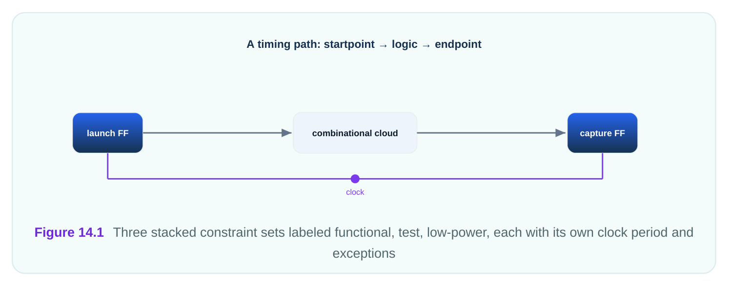
A mode captures how the chip is configured to behave. In functional mode the chip runs its normal job at its rated clock. In test mode the chip shifts test patterns through scan chains, often at a slower clock and with different paths active. In a low-power mode the chip may run at a reduced clock to save energy. Each mode has its own constraints because the active paths, clock speeds, and false-path lists differ. A path that is false in functional mode may be the most important path in test mode. So you write a separate constraint set, with its own clocks and exceptions, for each mode.
# standard SDC — portable across compliant tools
# Functional mode: full-speed clock
create_clock -name func_clk -period 4.00 [get_ports clk_in]
# Test mode (loaded separately): slower scan clock
create_clock -name scan_clk -period 12.50 [get_ports clk_in]| Mode | Typical clock period | What is active |
|---|---|---|
| Functional | 4.00 ns (250 MHz) | Normal datapaths |
| Test (scan) | 12.50 ns (80 MHz) | Scan chains, test logic |
| Low-power | 10.00 ns (100 MHz) | Reduced subset, gated clocks |
Corners: Process, Voltage, Temperature
A corner fixes the physical conditions the silicon faces. Process is the manufacturing variation; chips come out slightly fast or slow. Voltage is the supply level, which may droop or rise. Temperature is how hot or cold the chip runs. Each combination changes gate delay. Two corners matter most. A slow corner (slow process, low voltage, often hot) makes gates slow and stresses setup, because data may arrive late. A fast corner (fast process, high voltage, often cold) makes gates fast and stresses hold, because data may arrive too early. Sign-off checks both, plus typical conditions. Corners are not set with SDC commands. They come from the timing libraries you load, each characterized at a specific PVT point. The same SDC constraints are evaluated against each corner's library.
| Corner | Process | Voltage | Temp | Stresses |
|---|---|---|---|---|
| Slow | Slow | 0.81 V | 125 C | Setup |
| Fast | Fast | 0.99 V | -40 C | Hold |
| Typical | Nominal | 0.90 V | 25 C | Reference |
The Mode by Corner Grid
Modes and corners are independent. Any mode can run at any corner. So they form a grid: rows of modes times columns of corners. Each cell of the grid is one scenario, a specific mode evaluated at a specific corner. The tool checks every scenario you ask it to. The grid is why coverage matters. Functional mode at the slow corner stresses functional setup. Functional mode at the fast corner stresses functional hold. Test mode at the slow corner stresses test setup, and so on. Each cell exercises a different combination of constraints and physical delays.
# Scenario count math
Modes  = 3   (functional, test, low-power)
Corners = 3  (slow, fast, typical)
Full grid scenarios = modes x corners = 3 x 3 = 9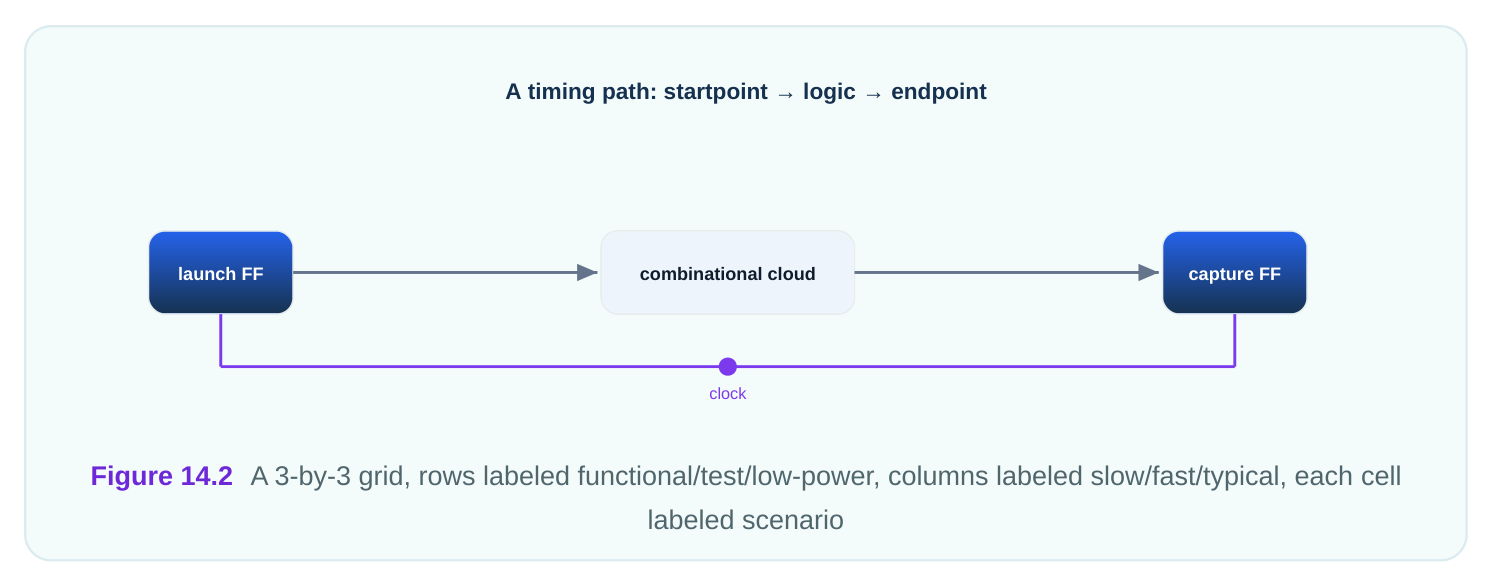
| Slow corner | Fast corner | Typical corner | |
|---|---|---|---|
| Functional | Func setup | Func hold | Func reference |
| Test | Test setup | Test hold | Test reference |
| Low-power | LP setup | LP hold | LP reference |
Why One Path Can Fail in Only One Scenario
A path's slack depends on both the mode's constraints and the corner's delays. Change either and the slack changes. So a path can pass eight scenarios and fail the ninth. Missing that one scenario means shipping a broken chip. Consider a worked example. A functional path has a data delay that is 4.10 ns at the slow corner but only 2.30 ns at the fast corner. The functional period is 4.00 ns; setup time 0.15 ns; uncertainty 0.20 ns.
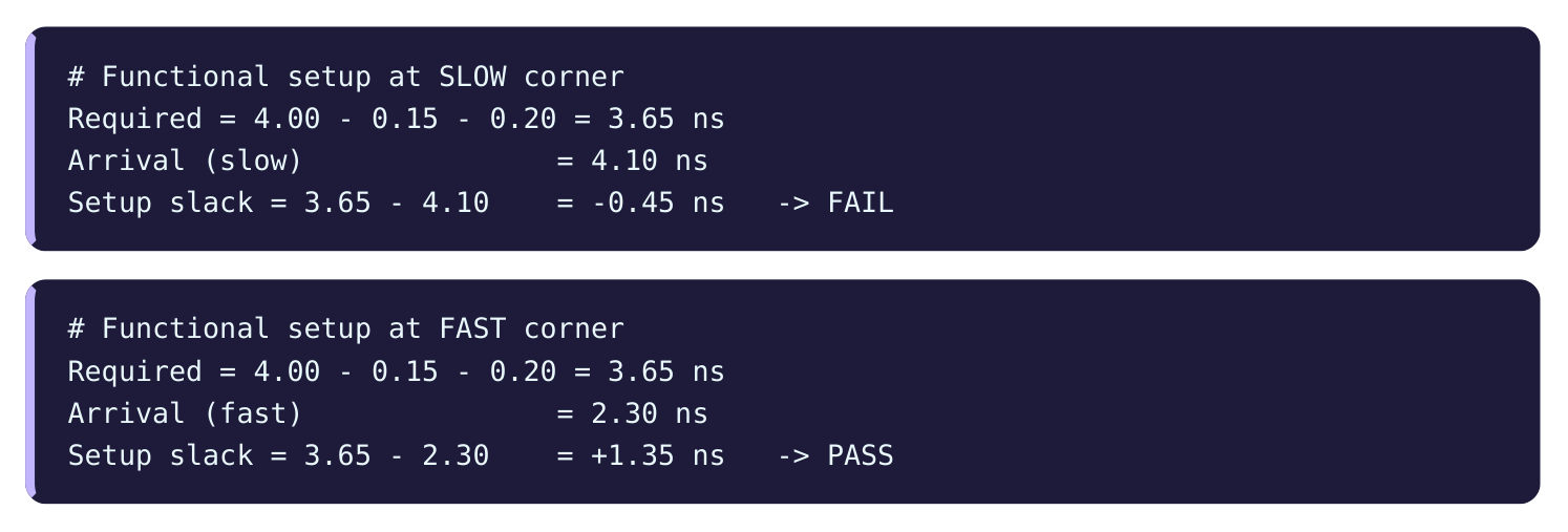
The same path fails setup at the slow corner but passes easily at the fast corner. If you had only run the fast corner, you would never see the failure. Now a hold view of a short path that is 0.55 ns slow and 0.22 ns fast, with hold time 0.10 ns at the fast corner where the hold edge is at 0.00 ns.
# Functional hold at FAST corner
Required = 0.00 + 0.10 = 0.10 ns
Arrival (fast short path) = 0.22 ns
Hold slack = 0.22 - 0.10  = +0.12 ns   -> PASS (tight)
If the fast short path dropped to 0.08 ns, hold slack would be 0.08 - 0.10 = -0.02 ns, a fast-corner-only hold failure that the slow corner would never reveal.
Scenario Count and Practical Coverage
Running every cell of a large grid is expensive. With 4 modes and 5 corners you have 20 scenarios, and each is a full timing run. Teams often trim the grid to the cells that can actually fail, a practice sometimes called scenario reduction. You keep the worst setup scenario, the worst hold scenario, and any mode-specific risk cells, and drop combinations that cannot be critical. For example, hold is usually worst at the fast corner, so you may skip hold checking at the slow corner. Setup is usually worst at the slow corner, so you may skip setup at the fast corner. This can cut a 9-cell grid to 5 or 6 active checks while still covering every real risk.
| Decision | Effect on scenarios |
|---|---|
| Full 3 modes x 3 corners | 9 scenarios |
| Drop hold at slow corner | -3 hold runs |
| Drop setup at fast corner | -3 setup runs |
| Practical kept set | ~5–6 active checks |
The danger of over-trimming is the same as everywhere in timing: if you drop a scenario that could fail, the failure ships. Reduction must be justified by the physics, not by schedule pressure. A good discipline is to write down the reason each dropped cell cannot be critical. "Hold at the slow corner is dropped because the fast corner always has shorter delays and therefore worse hold" is a defensible note. "Test mode at the typical corner is dropped to save runtime" is not, because runtime is not a physical argument. When the reasons are written next to the grid, a reviewer can challenge any weak ones. When they are only in someone's head, the weak ones survive until silicon proves them wrong, which is the most expensive possible time to find out.
# illustrative — names vary by tool
report_timing -scenario func_slow -delay_type max
report_timing -scenario func_fast -delay_type min
report_qor -scenarios {func_slow func_fast test_slow}
Interview Q&A
own constraints, such as functional, test, or low-power, each with its own clocks and exceptions. A corner is a set of physical conditions, process, voltage, and temperature (PVT), such as slow at 0.81 V and 125 C. Modes come from SDC; corners come from libraries.
both the mode's constraints and the corner's delays. The same path can pass eight scenarios and fail one. A functional path might have 4.10 ns delay at the slow corner (fails setup) but 2.30 ns at the fast corner (passes). You must check both.
voltage, hot) stresses setup, because gates are slow and data arrives late. The fast corner (fast process, high voltage, cold) stresses hold, because gates are fast and data arrives too early. Sign-off checks both.
so 3 × 3 = 9 scenarios. Each is one mode evaluated at one corner, and each is a full timing run. Teams often reduce this to the cells that can actually fail, perhaps 5 or 6.
corner with 0.10 ns hold time and the hold edge at 0.00 ns, giving slack 0.22 - 0.10 = +0.12 ns. If that path dropped to 0.08 ns, slack becomes 0.08 - 0.10 = -0.02 ns, a hold failure visible only at the fast corner.
the cells that can be critical, for example keeping setup at the slow corner and hold at the fast corner. The risk is dropping a scenario that could actually fail; that failure then ships. Reduction must rest on physics, not schedule.
Key Takeaways
- MMMC checks many situations at once: modes (functional, test, low-power) crossed with corners (PVT).
- Modes come from SDC constraints; corners come from characterized libraries; together they form scenarios.
- The slow corner stresses setup, the fast corner stresses hold, so both must be signed off.
- A single path can pass eight scenarios and fail one, so the grid count is modes × corners (e.g. 3 × 3 = 9).
- Scenario reduction trims the grid to critical cells, but over-trimming can ship a real, scenario- specific failure.
Comments
Leave a Reply