 ChipBuddy
← Home
ChipBuddy
← Home
MMMC Scenario Construction
MMMC Scenario Construction (Deep)
A modern chip must be timed in many situations at once. It runs in several operating jobs, called modes. It must work across several PVT corners. Checking one mode at one corner is not enough. You must cover the full grid of modes crossed with corners. This grid-based approach is called multimode multi-corner analysis, or MMMC for short. MMMC pairs each mode with each corner to form a "scenario." A scenario is one mode plus one corner plus the right constraints and libraries. The tool times each scenario. This chapter explains how scenarios are built, which SDC applies to each, how constraints are shared, why scenarios explode in number, how to prune them, and how analysis views tie it all together.
Modes, Corners, and Scenarios
A "mode" is one operating job, like normal mode or test mode. A "corner" is one PVT condition, like the slow corner or the fast corner. A "scenario" combines one mode with one corner. The scenario also pulls in the constraints for that mode and the libraries for that corner. Think of a small grid. Two modes and three corners give six cells. Each cell is one scenario. The tool runs every cell you ask for. Each cell has its own slack, because the mode changes the active paths and the corner changes the delays.
| Scenario | Mode | Corner | Drives |
|---|---|---|---|
| func_slow | functional | slow / low V | setup |
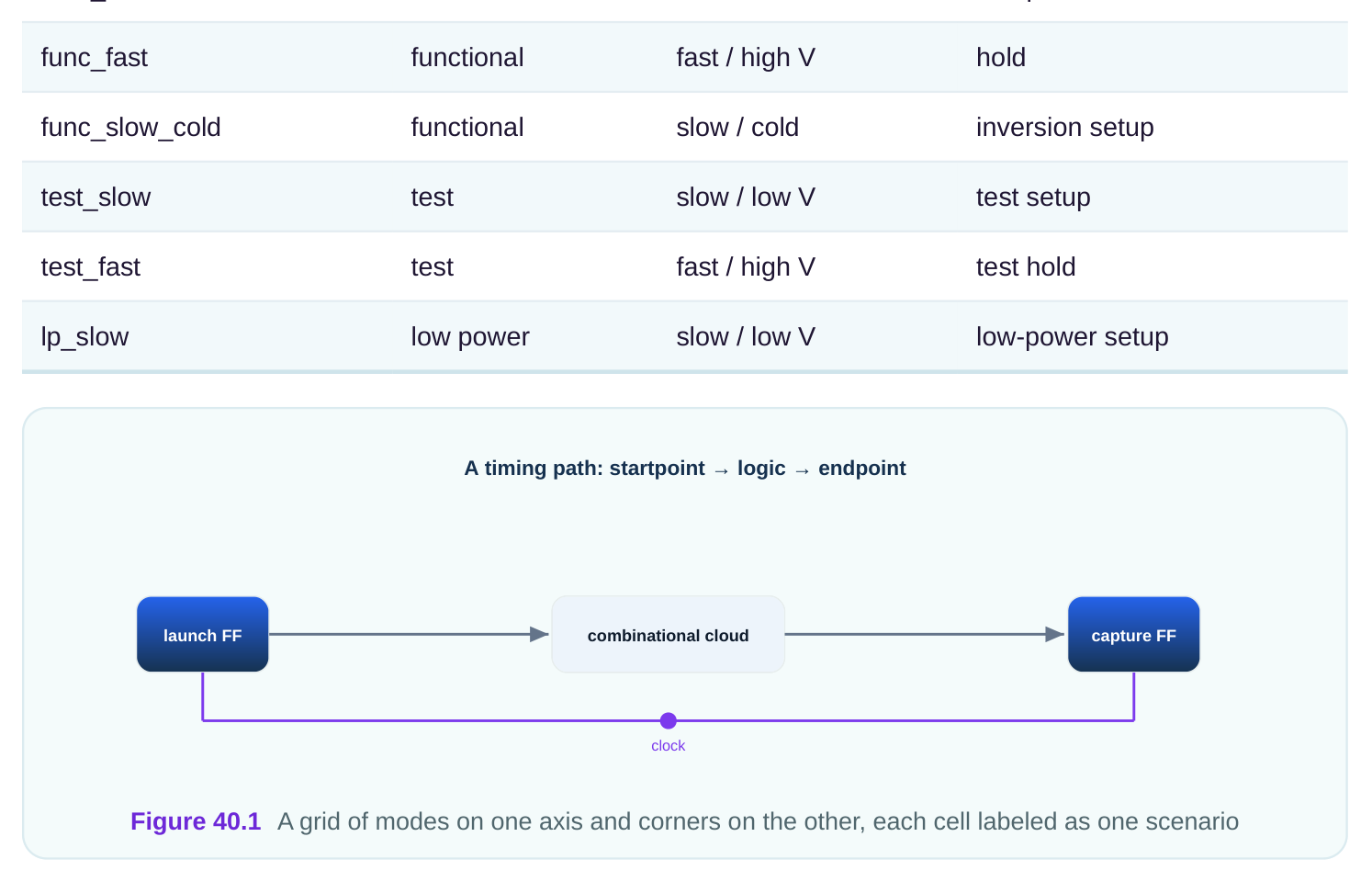
A scenario brings together three ingredients. The mode supplies the case-analysis values and any mode-specific exceptions. The corner supplies the libraries and the operating condition. The constraints supply the clocks and the path rules. The tool fuses these and times the result. Change any one ingredient and you have a different scenario.
Which SDC Applies Per Mode
Each mode has its own constraints. A functional mode uses the functional clocks and the functional case-analysis values. A test mode uses the test clock and the scan case-analysis values. You do not mix them. So the SDC for a mode is the set of constraints that describes that job. The corner does not usually change the SDC. The corner changes the libraries and the operating condition. So the same mode SDC is reused across all corners for that mode. The functional SDC runs against the slow library and against the fast library. Only the delay data changes.
| Ingredient | Changes with mode? | Changes with corner? |
|---|---|---|
| case-analysis values | yes | no |
| clock definitions | often yes | no |
| path exceptions | sometimes | no |
| libraries | no | yes |
| operating condition | no | yes |
# standard SDC — portable across compliant tools
# functional mode constraints, reused across corners
create_clock -name core_clk -period 2.713 [get_ports clk_in]
set_case_analysis 0 [get_ports test_mode]
set_input_delay 0.842 -clock core_clk [get_ports data_in]
This functional SDC sets the functional clock at 2.713 ns, holds test mode off, and gives an input delay. It runs unchanged against every functional corner. A separate test SDC would set the test clock and turn test mode on. A worked illustration. You have a functional SDC and a test SDC. You have a slow library and a fast library. The combinations are: functional plus slow, functional plus fast, test plus slow, test plus fast. That is four scenarios from two SDC files and two libraries. The two SDC files are written once and reused. This reuse is the whole point of separating mode constraints from corner data.
Shared Versus Unique Constraints
Some constraints are the same in every mode. Others differ by mode. Sorting these well saves huge effort. Put the shared constraints in one common file. Put the mode-specific ones in their own files. Then each mode loads the common file plus its own file. Shared constraints often include the basic clock period, the default input and output delays, and exceptions that hold in every mode. Unique constraints include case-analysis values, mode-only clocks, and exceptions that only apply in one job.
| Constraint | Usually shared | Usually unique |
|---|---|---|
| primary clock period | yes | no |
| input/output delays | yes | sometimes |
| case-analysis mode select | no | yes |
| test clock definition | no | yes (test only) |
| mode-only false paths | no | yes |
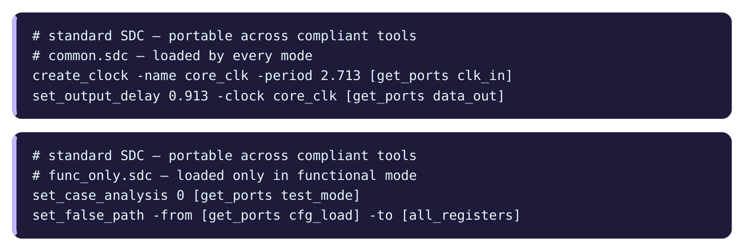
The common file holds what every mode needs. The mode file holds what only functional mode needs. The functional scenario loads both. The test scenario loads the common file plus its own test file. This layering keeps constraints consistent and avoids copying the same lines into many files. When the shared clock changes, you edit one line, not many.
Scenario Explosion and Pruning
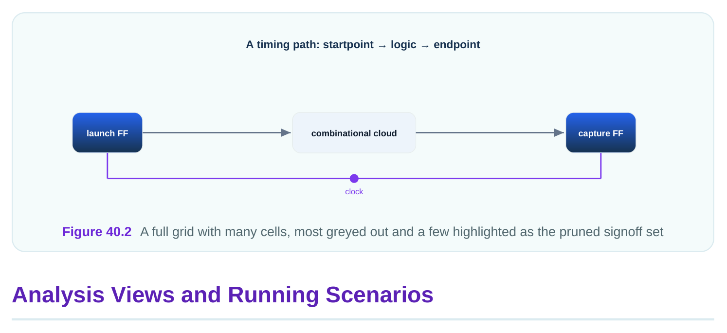
The grid grows fast. Modes times corners times other splits can reach a large count. If you have 4 modes and 5 corners, that is 20 scenarios. Add a split for two voltage modes and you reach 40. Each scenario costs runtime and memory. A full grid can take many hours and a lot of machines. Most cells in the grid are not worth running. Many are bounded by another cell. A high-voltage functional setup run is never worse than a low-voltage one, so you can drop it. A typical-corner run rarely bounds anything for signoff, so you drop it too. The craft is to keep only the cells that can be the worst case for some check.
| Full-grid cell | Keep or prune | Reason |
|---|---|---|
| functional / slow / setup | keep | classic setup worst |
| functional / fast / hold | keep | classic hold worst |
| functional / typical | prune | never the worst for signoff |
| test / slow / setup | keep | test setup worst |
| functional / high V / setup | prune | high V helps setup |
| low power / slow / setup | keep | unique low-power job |
A worked illustration with numbers. A project starts with 4 modes and 6 corners, giving 24 scenarios. The team applies pruning. They keep one setup corner and one hold corner per mode, plus one inversion setup corner for the two timing-critical modes. The kept count is: 4 modes times 2 base scenarios, which is 8, plus 2 inversion scenarios, which is 10. They drop 14 scenarios that are each bounded by a kept one. Runtime falls by more than half with no loss of coverage. This pruning is the everyday work of MMMC planning.
The tool ties a mode and a corner together with a named object, often called an analysis view. An "analysis view" names one scenario so the tool can run it, report it, and optimize it. You define each view once, then refer to it by name. A view points at three things: the mode constraints, the corner libraries, and whether it is a setup or hold context. You build a list of views. The tool then times every view in the list. Reports and optimization can target one view or all of them.
# illustrative — names vary by tool
create_corner -name slow -lib libs/cells_ss.lib
create_corner -name fast -lib libs/cells_ff.lib
create_mode   -name functional -sdc func.sdc
create_mode   -name test       -sdc test.sdc
create_view -name func_setup -mode functional -corner slow -check setup
create_view -name func_hold  -mode functional -corner fast -check hold
create_view -name test_setup -mode test       -corner slow -check setup
set_active_views {func_setup func_hold test_setup}
This sets up two corners, two modes, and three views, then makes those three views active. The tool times only the active views. The command names are local, so this block is tagged illustrative; the idea of pairing mode and corner into a named view is portable.
| View | Mode | Corner | Check |
|---|---|---|---|
| func_setup | functional | slow | setup |
| func_hold | functional | fast | hold |
| test_setup | test | slow | setup |
Views also let optimization see all scenarios at once. A good optimizer fixes a path so it passes in every active view, not just one. If you optimized one view alone, a fix might break another view. By
making the worst views active together, the tool balances them. A path that is tight for setup in the slow view and tight for hold in the fast view gets a fix that respects both. A worked illustration. A flop fails setup by 0.061 ns in the slow view. The optimizer wants to speed up the path. But the same flop has only 0.018 ns of hold margin in the fast view. If the optimizer speeds the path too much, it breaks hold. With both views active, the tool adds just enough speed to clear setup while keeping hold positive. The final result is positive slack in both views. That balance is the reason MMMC runs the worst views together rather than one at a time.
Interview Q&A
constraints and libraries. The mode sets the active paths, the corner sets the delays. The tool times each scenario separately, so each has its own slack.
condition, not the constraints. The same mode SDC is reused across all corners for that mode. Only the delay data swaps from one corner to the next.
mode in one shared file. Put mode-specific items, like case-analysis values and test clocks, in their own files. Each mode loads the shared file plus its own, which keeps constraints consistent and avoids duplication.
splits multiplies fast. Most cells are bounded by another, so they cannot be the worst case. Keep one setup and one hold corner per mode, add inversion corners where needed, and drop the rest.
type. The tool runs, reports, and optimizes by view. Defining views once lets you refer to each scenario by name.
another, like speeding a path to fix setup but breaking hold. With the worst views active together, the optimizer balances all of them, producing positive slack across every active view.
Key Takeaways
- A scenario pairs one mode with one corner, fusing the mode's active paths with the corner's delays into a single timed context.
- The corner changes libraries, not the SDC, so each mode's constraints are written once and reused across every corner for that mode.
- Shared constraints go in a common file and unique ones in per-mode files, keeping the whole set consistent and easy to update.
- Scenario count explodes quickly and must be pruned, keeping only the cells that can be the worst case for some check.
- Analysis views name each scenario and let optimization balance them, so a fix for one view does not silently break another.
Comments
Leave a Reply