 ChipBuddy
← Home
ChipBuddy
← Home
Quick Reference & Worked Examples
Quick Reference & Worked Examples
This chapter is the page you keep open while writing constraints. It gathers the commands you use most into one table, then walks through four worked examples with real arithmetic, and finishes with a complete small SDC script you can read top to bottom. Use it as a refresher, not a tutorial; the earlier chapters explain the why.
Command Cheat-Sheet
The table lists the common commands, what each does, and whether it is portable standard SDC or a reporting or run command whose exact name varies by tool.
| Command | Purpose | Type |
|---|---|---|
| create_clock | Define a clock with period and waveform | standard SDC (real) |
| create_generated_clock | Derive a divided or multiplied clock from a | standard SDC (real) |
source
set_input_delay State when an input is valid relative to a standard SDC (real)clock
set_output_delay State how much period downstream logic standard SDC (real)needs
set_false_path Remove a never-exercised path from standard SDC (real)analysis
set_multicycle_path	Allow a path more than one clock period	standard SDC (real)
set_clock_groups	Declare clocks related or asynchronous	standard SDC (real)
set_case_analysis	Fix a pin to a constant and propagate	standard SDC (real)
set_disable_timing	Turn off a specific timing arc	standard SDC (real)
set_max_transition	Cap how slowly a signal may switch	standard SDC (real)
set_max_capacitance	Cap the load a driver may see	standard SDC (real)
set_drive Set driver strength on an input port standard SDC (real)| group_path | Collect paths into a named report group | standard SDC (real) |
|---|---|---|
| report_timing | Show worst paths and slack | illustrative (varies by |
tool)
report_clocks List defined clocks illustrative (varies bytool)
report_ports -unconstrained List ports with no delay set illustrative (varies bytool)
Worked Example: A Clock Constraint
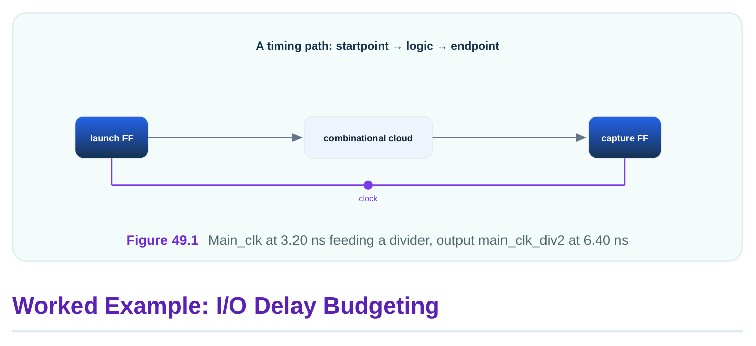
A design has a primary clock running at 312.5 MHz and an on-chip divider producing a half-rate clock. Step 1: convert frequency to period. 1000 / 312.5 = 3.20 ns. Step 2: the divider's output is half the rate, so its period is 6.40 ns. Step 3: declare the primary clock, then derive the divided one so it tracks the source.
# standard SDC — portable across compliant tools
# 312.5 MHz primary clock: period = 1000 / 312.5 = 3.20 ns
create_clock -name main_clk -period 3.20 [get_ports main_clk]
# Divide-by-two output is 6.40 ns, derived so it tracks main_clk
create_generated_clock -name main_clk_div2 \
-source [get_ports main_clk] -divide_by 2 [get_pins div_reg/Q]
If main_clk later changes to 3.10 ns, main_clk_div2 automatically becomes 6.20 ns. That is the payoff of deriving instead of declaring a second independent clock.
A 250 MHz interface, period 1000 / 250 = 4.00 ns, connects the chip to external logic. The external source guarantees data valid no later than 1.70 ns after the clock edge and stable until 0.50 ns after the edge. On the output side, the external receiver needs 1.30 ns of setup before its capturing edge. For the input, max delay is 1.70 ns and min delay is 0.50 ns. The on-chip path then has 4.00 minus 1.70 = 2.30 ns to capture, before setup and skew. For the output, output delay is 1.30 ns, leaving 4.00 minus 1.30 = 2.70 ns for the on-chip path to produce the output.
# standard SDC — portable across compliant tools
create_clock -name if_clk -period 4.00 [get_ports if_clk]
# Input: latest valid 1.70 ns after edge, earliest 0.50 ns after edge
set_input_delay  -clock if_clk -max 1.70 [get_ports rx_data*]
set_input_delay  -clock if_clk -min 0.50 [get_ports rx_data*]
# Output: external receiver needs 1.30 ns of the period
set_output_delay -clock if_clk -max 1.30 [get_ports tx_data*]| Side | Delay set | Period left on-chip |
|---|---|---|
| Input max | 1.70 ns | 4.00 - 1.70 = 2.30 ns |
| Input min | 0.50 ns | used for hold |
| Output max | 1.30 ns | 4.00 - 1.30 = 2.70 ns |
The on-chip logic must fit inside 2.30 ns on the input side and 2.70 ns on the output side. If it does not, you either speed up the logic or renegotiate the external numbers.
Worked Example: Multicycle Setup and Hold
A slow multiply block produces a result used only every third cycle. The clock is 2.80 ns. The path can take up to three periods. Setup: a multicycle of 3 gives 3 times 2.80 = 8.40 ns for the setup check instead of one period of 2.80 ns. Hold: you must set hold to N minus 1, which is 2, to pull the hold check back to one cycle after launch at 2.80 ns rather than three cycles at 8.40 ns.
# standard SDC — portable across compliant tools
# Path may take 3 cycles; setup gets 3 x 2.80 = 8.40 ns
set_multicycle_path 3 -setup -from [get_pins mult_reg/Q] -to [get_pins res_reg/D]
# Hold must be N-1 = 2 so the hold check lands at 2.80 ns, not 8.40 ns
set_multicycle_path 2 -hold -from [get_pins mult_reg/Q] -to [get_pins res_reg/D]| Check | Multiplier | Edge time | Window |
|---|---|---|---|
| Setup | 3 | 8.40 ns | path has 8.40 ns minus setup |
| Hold (correct) | 2 | 2.80 ns | one cycle after launch |
| Hold (if forgotten) | default | 8.40 ns | impossible, false violation |
Forgetting the hold line is the classic trap. The default hold check would land at 8.40 ns and demand the data hold stable for three full cycles, an impossible requirement that shows up as unfixable hold violations.
A Full Small SDC Script
This is a complete, readable constraint file for a small block with one primary clock, one divided clock, budgeted I/O, an asynchronous reset, one false path, and basic design rules. Real portable commands are tagged; the final reporting lines are illustrative.
# standard SDC — portable across compliant tools
# ---- Central values ----
set MAIN_PERIOD 3.20   ;# 312.5 MHz
# ---- Clocks ----
create_clock -name main_clk -period $MAIN_PERIOD [get_ports main_clk]
create_generated_clock -name main_clk_div2 \
-source [get_ports main_clk] -divide_by 2 [get_pins div_reg/Q]
# ---- Treat reset as an ideal network ----
set_ideal_network [get_ports rst_n]
# ---- Input and output delays (budgeted) ----
set_input_delay  -clock main_clk -max 1.40 [get_ports data_in*]
set_input_delay  -clock main_clk -min 0.45 [get_ports data_in*]
set_output_delay -clock main_clk -max 1.10 [get_ports data_out*]
# ---- Safety net so no port is left unconstrained ----
set_input_delay  -clock main_clk 1.00 [all_inputs]
set_output_delay -clock main_clk 1.00 [all_outputs]
# ---- Exceptions ----
# Asynchronous reset is not a timed data path
set_false_path -from [get_ports rst_n]
# Slow status path used every other cycle: multicycle 2 with hold 1
set_multicycle_path 2 -setup -from [get_pins stat_reg/Q] -to [get_pins cap_reg/D]
set_multicycle_path 1 -hold  -from [get_pins stat_reg/Q] -to [get_pins cap_reg/D]
# ---- Mode pruning: force functional mode, exclude scan ----
set_case_analysis 0 [get_ports scan_en]
# ---- Design rules ----
set_max_transition  0.30 [current_design]
set_max_capacitance 0.16 [current_design]
# illustrative — names vary by tool
# ---- Sanity reporting after reading the constraints ----
report_clocks
report_ports -unconstrained
report_timing -max_paths 20
Read the script top to bottom and you see the order that keeps a constraint file safe: central values first, then clocks, then the I/O budget with a safety net, then exceptions, then mode pruning, then design rules, and finally the reporting that proves coverage. Everything that affects timing comes before the reports that check it.
Key Takeaways
- Keep the cheat-sheet handy: most work uses a dozen portable commands, with reporting names varying by tool.
- Frequency to period is 1000 / MHz: 312.5 MHz is 3.20 ns, and a divide-by-two of it is 6.40 ns.
- I/O budgeting is subtraction: the on-chip path gets the period minus the I/O delay you set.
- Multicycle needs both lines: setup of N and hold of N-1, or you create impossible hold checks.
- Order a script safely: values, clocks, I/O with a safety net, exceptions, mode pruning, design rules, then reporting.
Comments
Leave a Reply