Datapath Building Blocks
Building Blocks That Do the Math
A processor's datapath does the arithmetic. It adds, shifts, compares, and multiplies. These functions are built from logic gates. But how you arrange the gates matters a lot. A clever structure is fast and small. A naive one is slow and big. This chapter covers the core datapath blocks. It focuses on the ideas an interviewer asks about.
The Adder: the Heart of Arithmetic
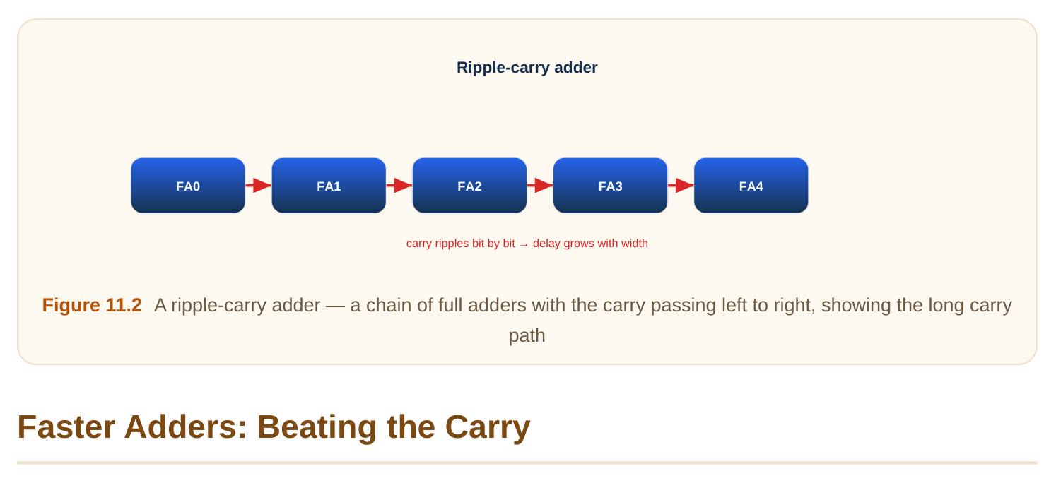
Addition is the most common datapath operation. A 1-bit adder is a full adder. It takes two bits plus a carry-in. It outputs a sum bit and a carry-out. To add many bits, you chain full adders. The carry ripples from one bit to the next. This is a ripple-carry adder (carry passes bit by bit). It is small and simple. But it is slow. The carry must travel through every bit. So delay grows with the number of bits.
Worked example — ripple-carry delay
Say each full adder adds 0.12 ns of carry delay. For an 8-bit adder, the carry passes through 8 stages. Worst-case delay ≈ 8 × 0.12 = 0.96 ns. For 32 bits it would be about 32 × 0.12 = 3.84 ns. That linear growth is the problem.
The carry chain is the bottleneck. Faster adders attack it. The trick is to compute carries in parallel, not one by one.
- Carry-lookahead adder: computes each carry directly from the inputs using "generate" and "propagate" signals. Delay grows much more slowly, roughly with the logarithm of bit count.
- Carry-select adder: computes two results per block (one for carry-in 0, one for carry-in 1). It then picks the right one when the real carry arrives. This trades area for speed.
- Prefix adders (tree adders): arrange the carry logic as a balanced tree. They give log-depth delay and are common in fast designs. The pattern: spend more gates to shorten the carry path. Bigger, faster. The right choice depends on the speed and area budget.
| Adder type | Speed | Area | Idea |
|---|---|---|---|
| Ripple-carry | slow (linear) | smallest | carry passes bit by bit |
| Carry-lookahead | fast (log) | larger | compute carries in parallel |
| Carry-select | fast | larger | precompute both, then pick |
| Prefix/tree | fastest (log) | largest | carry as a balanced tree |
Worked example — log vs linear
Compare a 32-bit ripple adder to a tree adder. The ripple version is about 32 carry stages deep. A tree version is about log2(32) = 5 levels deep. So the tree path is roughly 6× shorter. That is why fast processors use tree adders despite their larger area.
The Shifter: Moving Bits
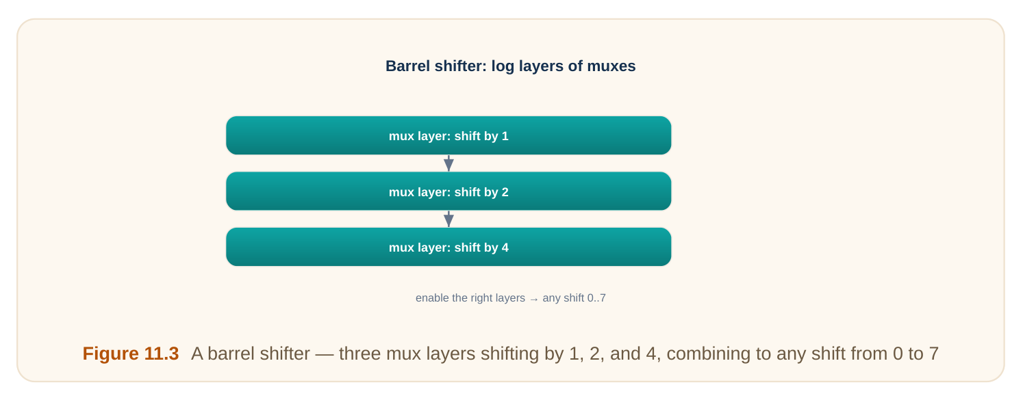
A shifter moves bits left or right. Shifting left by N multiplies by 2^N. Shifting right divides by 2^N. So shifters help with multiply and divide. A barrel shifter shifts by any amount in one step. It is built from layers of multiplexers (switches that pick one of several inputs). Each layer shifts by a power of two: 1, 2, 4, 8, and so on. Turning the right layers on gives any shift amount.
Worked example — barrel-shifter layers
To shift up to 7 positions, you need shifts of 1, 2, and 4. That is 3 mux layers (since 1 + 2 + 4 = 7). To shift up to 15, you need layers of 1, 2, 4, 8 — that is 4 layers. In general, an N-bit shift range needs about log2(N) layers. Each layer adds a little delay.
The Multiplier: Adding Many Times
Multiplication is repeated addition. A simple multiplier makes partial products. Each partial product is one input ANDed with one bit of the other input. Then it sums all the partial products, shifted into place. The slow part is summing many partial products. Fast multipliers speed this up.
- Array multiplier: a regular grid of adders. Simple and regular, but delay grows with size.
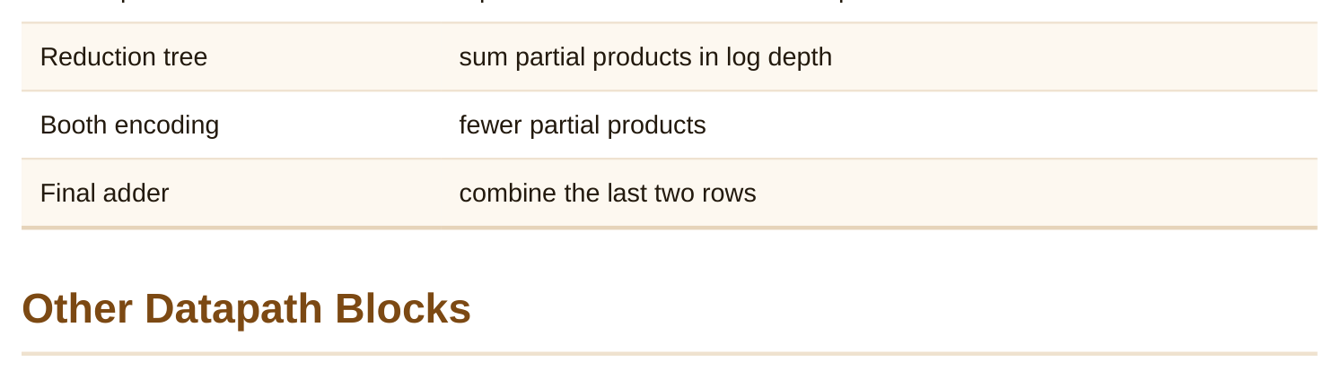
- Tree multiplier (e.g., Wallace/Dadda style): sums partial products in a tree, giving log-depth reduction. Faster but less regular.
- Booth encoding: a trick that cuts the number of partial products, roughly in half. Less to add means faster. The final step is usually one fast adder to combine the last two rows. So a fast multiplier mixes a reduction tree with a fast final adder. Multiplier part Job Partial products input AND each bit of the other input
A datapath has more than adders and multipliers.
- Comparators: check equal, greater, or less. Equality is a chain of XNORs. Magnitude compare often reuses a subtractor.
- Multiplexers: pick one of several inputs. The building block of selection and shifting.
- Counters and incrementers: a special, cheaper adder that just adds one.
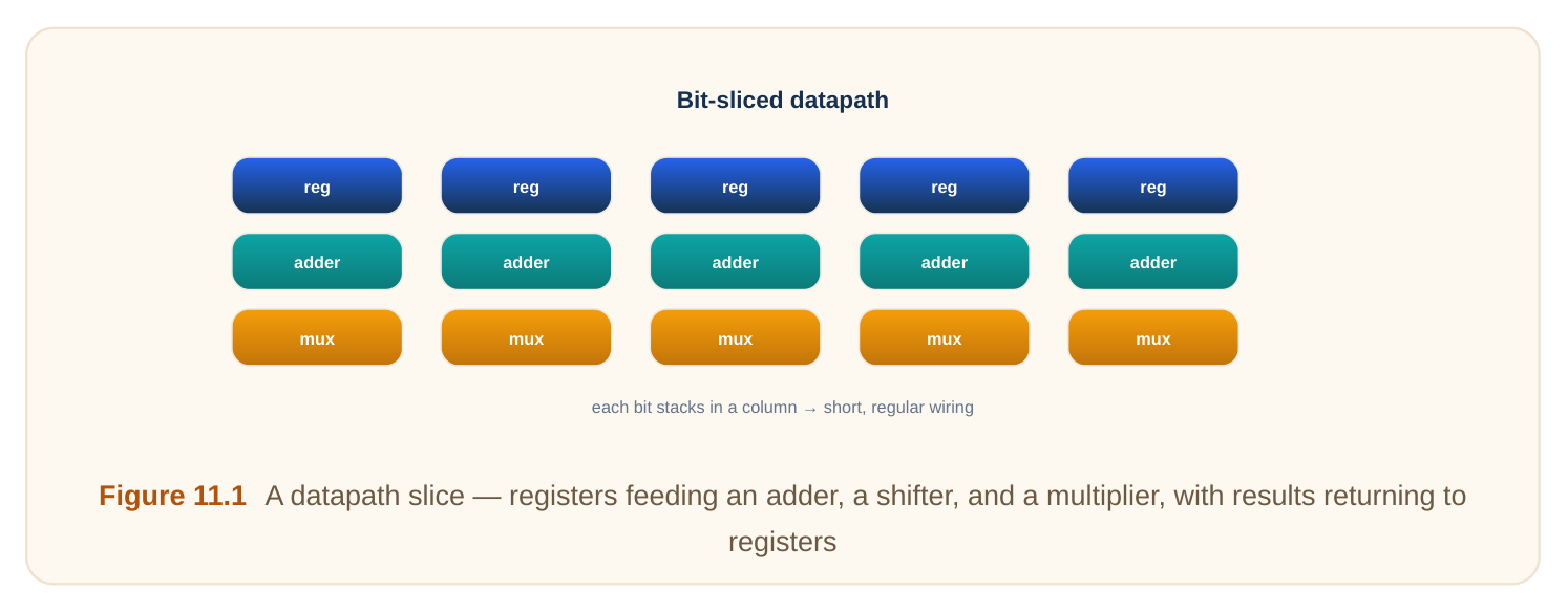
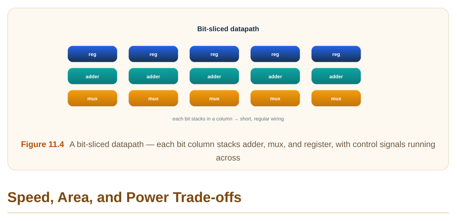
- ALU (arithmetic logic unit): combines add, subtract, AND, OR, and more into one block with a select. These blocks share signals and structure. Good datapath layout lines them up in bit-sliced columns. Each bit's logic stacks in a neat column. This keeps wires short and regular.
Every datapath choice trades the same three things. Speed, area, and power.
- Faster structures (tree adders, Booth multipliers) use more gates. More gates means more area and more power.
- Smaller structures (ripple adders, array multipliers) save area and power. But they are slower.
- Pipelining (splitting a long operation across clock stages) raises throughput. But it adds registers and latency. The right block depends on the budget. A low-power sensor chip may pick small, slow blocks. A high- end processor picks large, fast ones. Goal Typical choice Maximum speed tree adder, Booth tree multiplier, pipelining Minimum area/power ripple adder, array multiplier Balanced carry-select adder, moderate pipelining
Interview Q&A
every bit in sequence, so delay grows linearly with bit count. Faster adders (carry-lookahead, carryselect, prefix/tree) compute carries in parallel, cutting the carry path to roughly log depth, at the cost of more gates and area.
from layers of multiplexers, each shifting by a power of two (1, 2, 4, …). Enabling the right layers produces any shift. An N-position range needs about log2(N) layers.
(Wallace/Dadda style) to add the partial products in log depth instead of linearly, often with Booth encoding to roughly halve the number of partial products, finishing with one fast adder for the last two rows.
structures use more gates, so they cost more area and power; smaller structures are slower. The right block depends on the design's speed, area, and power budget, plus whether pipelining is worth the added registers and latency.
between blocks short and regular. Control signals run across the slices. This regular structure improves density, timing predictability, and routability compared to random placement.
Key Takeaways
- The adder is the core block; ripple-carry is small but slow (linear), while lookahead/select/tree adders are fast (log depth) at higher area.
- A barrel shifter shifts any amount in one step using log2(N) mux layers; shifting implements multiply/divide by powers of two.
- Multipliers form partial products, then sum them with a reduction tree (and Booth encoding) plus a fast final adder.
- Datapaths also use comparators, muxes, counters, and ALUs, laid out in bit slices for short, regular wiring.
- Every choice trades speed vs area vs power; pick the block that fits the budget, and pipeline for throughput.
Comments
Leave a Reply