 ChipBuddy
← Home
ChipBuddy
← Home
Power — Dynamic, Short-Circuit & Leakage
Leakage
Power is now the top concern in chip design. A fast chip that burns too much power is useless. Phones drain. Servers overheat. Batteries die. This chapter explains where power goes in CMOS (Complementary Metal-Oxide-Semiconductor) circuits. We split it into three buckets. We then show how to cut each one. By the end, you can compute power and reason about trade-offs.
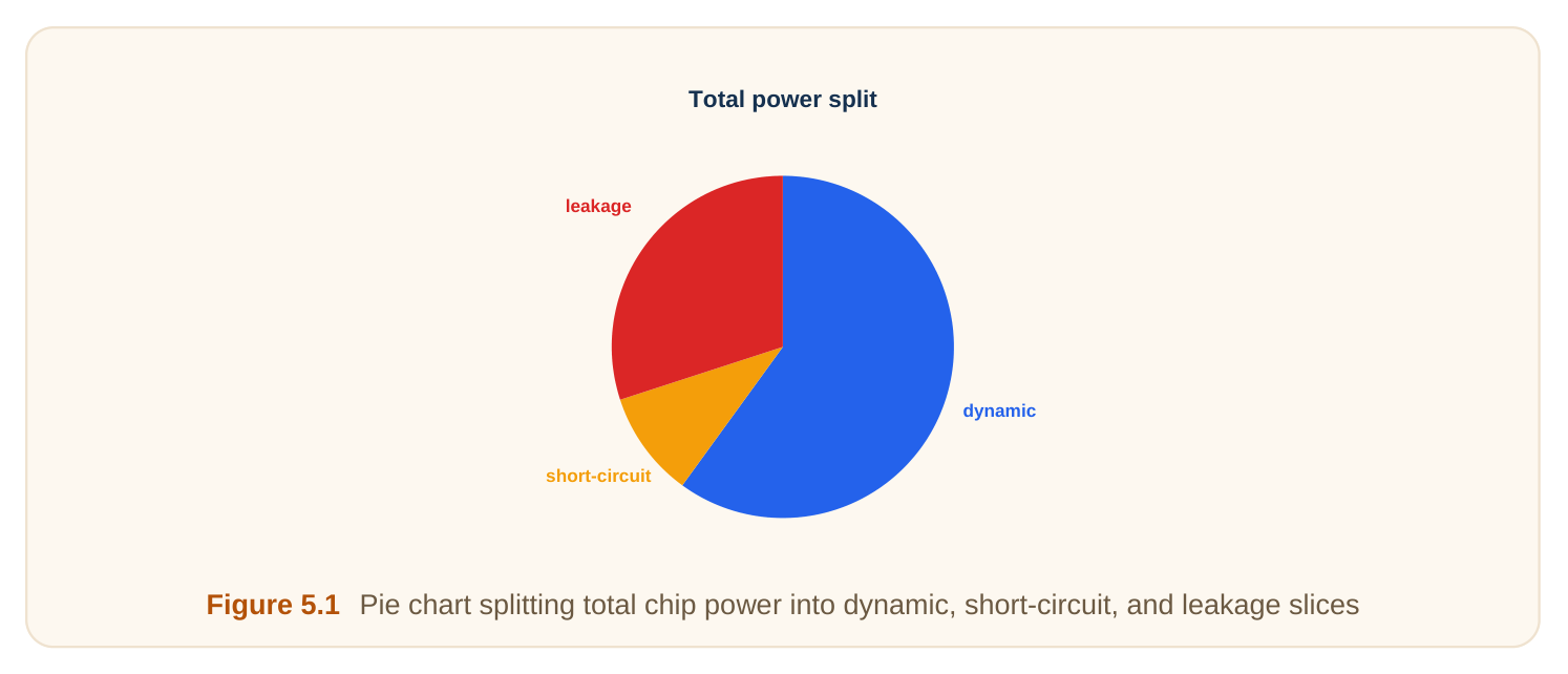
The Three Components of Power
Total power in a CMOS chip comes from three sources. Each has a different cause. Each needs a different fix. Dynamic power (switching power) is spent when gates switch. Every time an output flips, charge moves. That charge movement costs energy. No switching means no dynamic power. Short-circuit power (crowbar power) is spent during a transition. For a brief moment, both transistor networks conduct. Current flows straight from supply to ground. It is wasted. Static leakage power (standby power) is spent even when nothing switches. Transistors are not perfect switches. Tiny currents trickle through when "off." This drain is always on. Here is the high-level map.
| Power type | When it happens | Main cause | Main lever |
|---|---|---|---|
| Dynamic | During output transitions | Charging load capacitance | Lower voltage, clock gating |
| Short-circuit | During the edge | Both networks conduct briefly | Sharper slew (faster edges) |
| Leakage | All the time | Imperfect "off" transistors | Multi-Vt, power gating |
Think of a water system. Dynamic power is water you pump to fill tanks. Short-circuit power is water spilled while a valve flips. Leakage is a slow drip from a closed tap. The balance between these shifted over time. In older, larger chips, dynamic power ruled. Leakage was tiny and ignored. As transistors shrank, leakage grew fast. In some idle chips, leakage now rivals dynamic power. This matters for how you optimize. A busy processor is dominated by dynamic power. An idle sensor chip is dominated by leakage. You must know your workload before you pick a fix.
Power and energy are not the same. Power is the rate of energy use, in watts. Energy is power times time, in joules. A battery stores energy. A heat sink handles power. Interviewers often probe this difference.
Dynamic Power: The C·V²·f Engine
Dynamic power is usually the biggest piece. It comes from charging and discharging capacitance. Every wire and gate input has capacitance (its ability to store charge). Call it the load capacitance, C_L. When the output rises, the supply charges C_L. When the output falls, that charge dumps to ground. Each full charge-discharge cycle costs energy equal to C_L · V_DD². Here V_DD is the supply voltage. The voltage is squared. This is the key fact. If a node toggles f times per second, its power is:
P_dynamic = α · C_L · V_DD² · f
The term α is the activity factor. It is how often a node actually toggles. A value of 1 means it flips every clock edge. A value of 0.1 means it flips one cycle in ten.
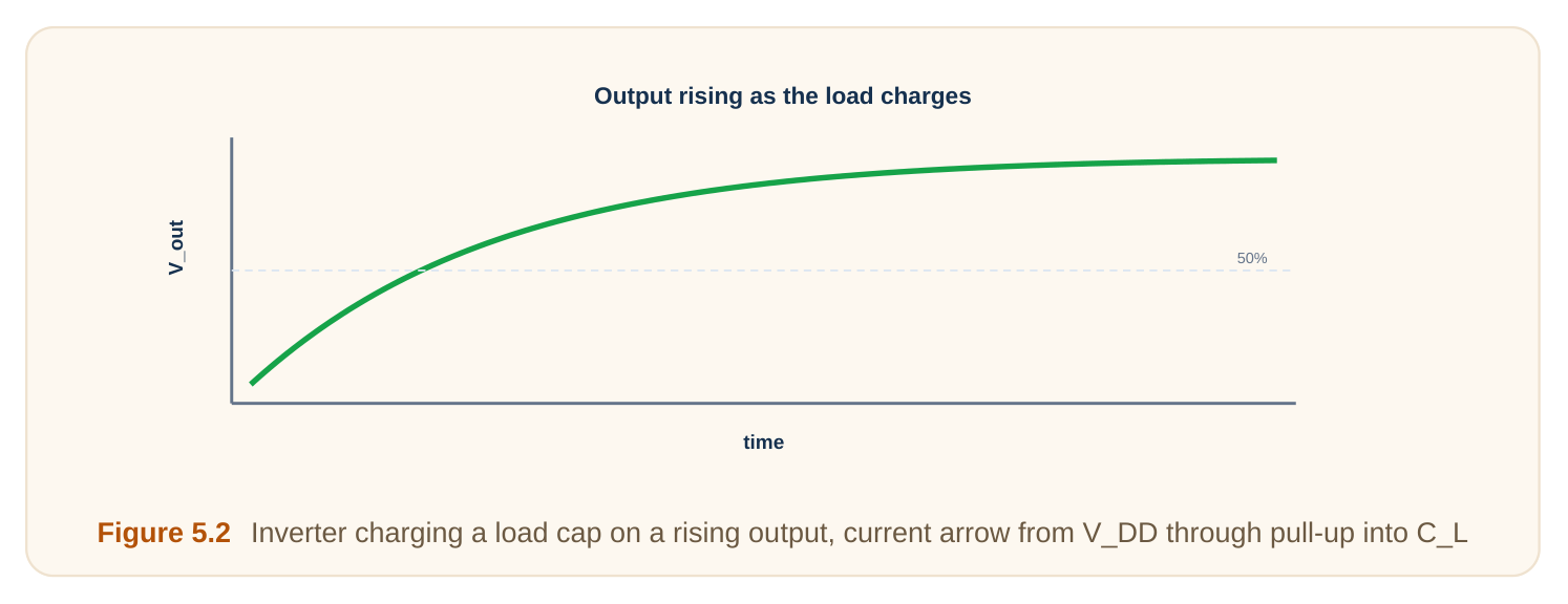
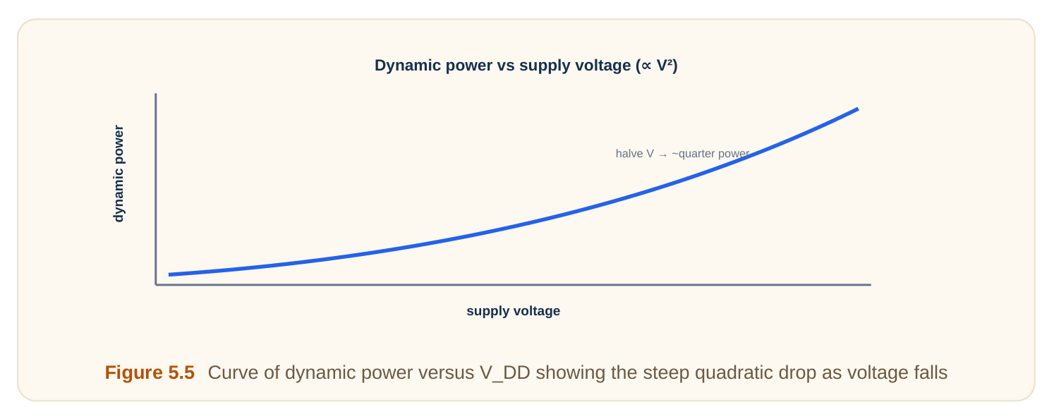
Why does V_DD square matter so much? Halving the voltage cuts dynamic power to one quarter. That is a huge win. We return to this later. The activity factor is the design knob you control most. Data buses can have α near 0.5. A clock line has α of 1, since it toggles every cycle. Clocks are power hogs for this reason. A small note on the math. A full toggle means a rise and a fall. The rise stores energy C_L · V_DD². The fall releases it to ground. We charge the cap once per up-down pair. So the energy per cycle is C_L · V_DD², and the formula counts that. Where does C_L come from? It is the sum of several things. The output cap of the driving gate. The wire cap of the routing. The input cap of every gate it drives. Long wires and high fan-out raise C_L. So good floorplanning cuts dynamic power too.
Glitches add hidden dynamic power. A glitch is a brief, unwanted toggle. It happens when inputs arrive at slightly different times. Each glitch charges and discharges a cap for nothing. Balanced logic paths reduce glitches. Below are the factors that drive dynamic power.
| Factor | Symbol | Effect on power | Notes |
|---|---|---|---|
| Activity factor | α | Linear | How often the node toggles |
| Load capacitance | C_L | Linear | Wire plus fan-out gate inputs |
| Supply voltage | V_DD | Squared | The strongest single lever |
| Frequency | f | Linear | Clock rate |
Short-Circuit Power: The Brief Crowbar
In a CMOS gate, the pull-up network and pull-down network should never both conduct. One pulls the output high. The other pulls it low. But input edges are not instant. They ramp over some time. During that ramp, the input sits between voltages. For a short window, both networks turn on together. When both conduct, current flows directly from V_DD to ground. This current does no useful work. It just heats the chip. We call it short-circuit or crowbar current.
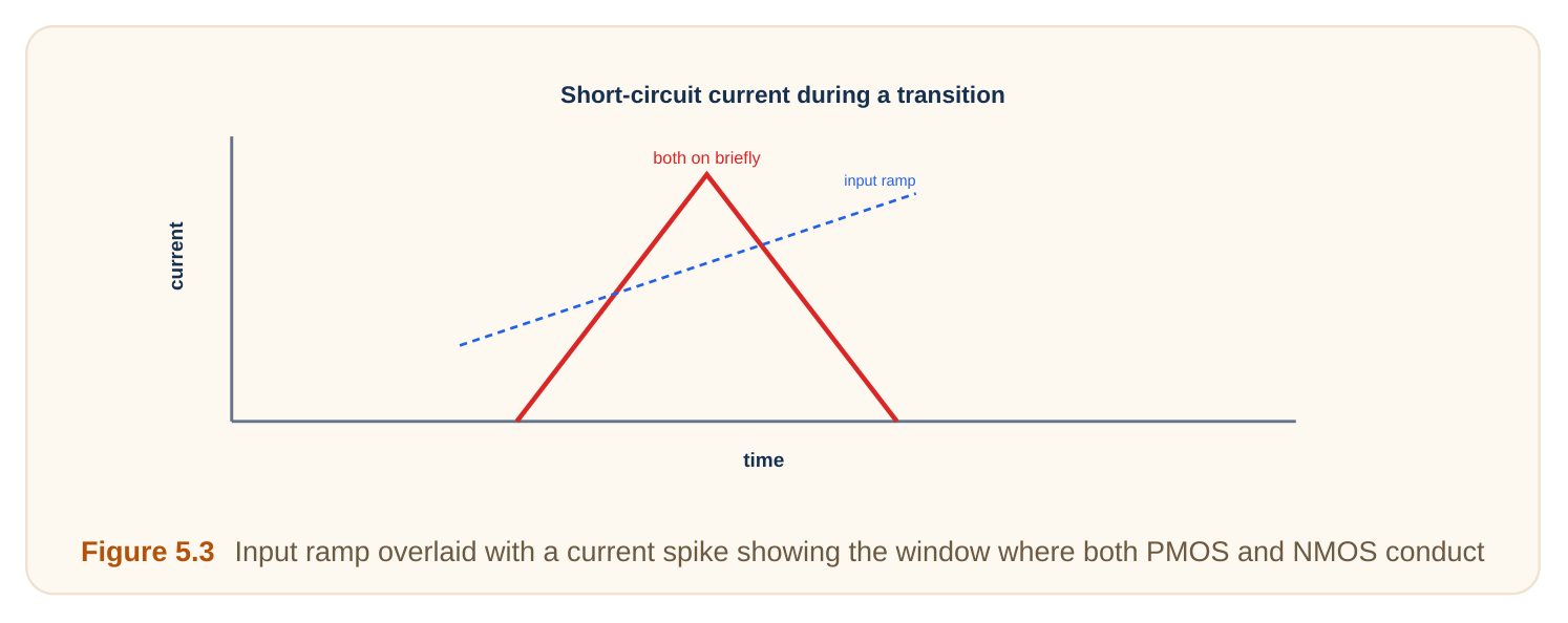
How big is this loss? It depends on edge speed. Slow input edges keep the gate in the conducting window longer. So slow edges make short-circuit power worse. Fast, sharp edges shrink the window. The gate snaps through it. Less crowbar current flows. This is why slew control (managing edge sharpness) matters. A rule of thumb: keep input edges as fast as the output edges. Balanced slews keep short-circuit power small. In a well-designed chip, it is often under 10 percent of dynamic power.
Short-circuit power also depends on the gap between V_DD and the thresholds. If V_DD is barely above the sum of the two thresholds, the conducting window nearly vanishes. At low voltage, shortcircuit power becomes almost negligible. This is a quiet bonus of voltage scaling. There is a design tension here. Very weak drivers give slow edges and high crowbar loss. Very strong drivers cost area and their own dynamic power. The fix is sizing each buffer to keep slews reasonable, not extreme. Balance beats extremes.
Leakage: The Always-On Drain
Leakage flows even with no switching. The chip can sit idle and still burn power. Two kinds dominate. Subthreshold leakage flows through an "off" transistor. A transistor turns on above its threshold voltage, V_t. Below V_t, it does not fully shut. A small current still leaks across. Subthreshold leakage rises sharply as V_t drops. Lower V_t makes transistors faster. But it leaks much more. This is a core trade-off. Gate leakage flows through the gate oxide. The oxide is a thin insulator under the gate. At small nodes, it became only a few atoms thick. Electrons tunnel straight through it.
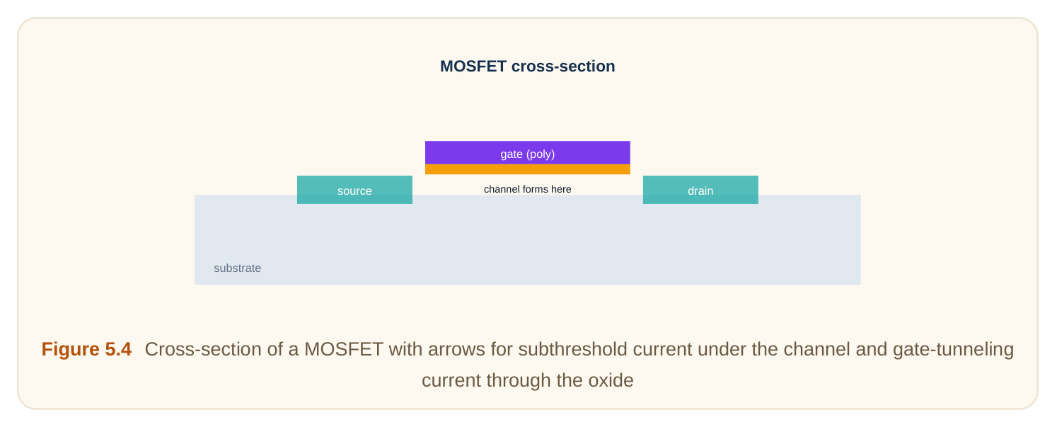
Why did leakage explode at small nodes? Two reasons. First, voltages dropped, so V_t had to drop too, raising subthreshold leakage. Second, oxides got thinner, raising gate tunneling. High-k dielectrics later helped cut gate leakage. There is also a smaller third type. Junction leakage flows across reverse-biased diodes inside the device. It is usually minor next to the other two. We mention it for completeness. Temperature makes leakage worse. Subthreshold leakage rises sharply as the chip heats up. A hot chip leaks more, which heats it further. This feedback loop is called thermal runaway risk. Good cooling and power management hold it in check. Leakage is insidious. It scales with the number of transistors. Modern chips have billions. A tiny pertransistor leak adds up to watts. And it never stops.
Levers to Cut Each Power Type
Each power component has its own fix. Match the lever to the problem. Lower the supply voltage. This is the strongest knob. Dynamic power falls with the square. Leakage also drops. The cost is speed: lower voltage means slower gates. Clock gating. Turn off the clock to idle blocks. This drives α to zero for those nodes. No toggling, no dynamic power. It is cheap and widely used. Multi-Vt cells. Use high-V_t cells on non-critical paths. They leak far less. Use low-V_t cells only where speed is needed. This balances leakage against timing. Power gating. Switch off power to idle blocks entirely. A header or footer switch cuts the supply. This kills leakage in that block. Waking it back up takes time, though. Slew control. Keep edges sharp and balanced. This shrinks the short-circuit window. Good buffering and sizing help here. Dynamic voltage and frequency scaling (DVFS). Adjust voltage and clock on the fly. When the workload is light, drop both. When it spikes, raise them. This tracks demand and saves power during idle stretches. Body biasing. Adjust the transistor body voltage to nudge V_t. Raise V_t when idle to cut leakage. Lower it when speed is needed. This gives a runtime leakage knob. The table below maps techniques to the power they cut.
| Technique | Cuts dynamic | Cuts short-circuit | Cuts leakage |
|---|---|---|---|
| Lower V_DD | Yes (big) | Yes | Yes |
| Clock gating | Yes | Indirectly | No |
| Multi-Vt cells | No | No | Yes |
| Power gating | No | No | Yes (big) |
| Slew control | No | Yes | No |
The Energy-vs-Speed Trade-Off
You cannot cut power for free. Most levers cost speed. Lower voltage saves dynamic power. But gates switch slower at low voltage. So the chip runs slower. You trade speed for energy. This is why voltage scaling is the strongest knob. It hits the squared term. Drop V_DD a little and dynamic power drops a lot. The speed loss is only linear-ish. The energy win usually beats the speed loss.
Designers exploit this with multiple voltage domains. Critical blocks run at high voltage for speed. Lazy blocks run at low voltage to save power. This is voltage islands.
The takeaway: when you need to save power, look at voltage first. Then activity. Then leakage techniques.
Worked Example 1: Dynamic Power From Scratch
Let us compute dynamic power for one node. Given values: - Activity factor α = 0.2 - Load capacitance C_L = 30 fF (femtofarads, 30 × 10⁻¹⁵ F) Supply voltage V_DD = 1.0 V - Frequency f = 2 GHz (2 × 10⁹ Hz) Apply the formula: P = α · C_L · V_DD² · f P = 0.2 × (30 × 10⁻¹⁵) × (1.0)² × (2 × 10⁹) P = 0.2 × 30 × 2 × 10⁻¹⁵⁺⁹ P = 12 × 10⁻⁶ W = 12 µW So one node burns 12 microwatts. Now scale up. A million such nodes burn 12 watts. This shows why per-node power matters.
Worked Example 2: Halving the Supply Voltage
Take the same node. Now drop V_DD from 1.0 V to 0.5 V. Keep everything else fixed. New power: P_new = 0.2 × (30 × 10⁻¹⁵) × (0.5)² × (2 × 10⁹) The only change is V_DD². We go from 1.0² = 1.0 to 0.5² = 0.25. P_new = 12 µW × 0.25 = 3 µW Halving voltage cut power to one quarter. We saved 75 percent of dynamic power. That is the squared term at work.
The catch: gates run slower at 0.5 V. We may have to lower the frequency too. If we also halve f, power drops to 1.5 µW. But the chip now does half the work per second.
Worked Example 3: Clock-Gating Savings
A block has 100,000 flip-flops. Each flip-flop and its clock pin burn dynamic power at α = 1, since the clock toggles every cycle. Say the clock distribution to this block burns 8 mW when fully active. Suppose the block is actually busy only 30 percent of the time. The rest of the time it is idle but still clocked. Without clock gating, the clock runs always. Power = 8 mW, full time. With clock gating, we stop the clock when idle. The clock effectively runs only 30 percent of the time. Clock power ≈ 8 mW × 0.30 = 2.4 mW Savings = 8 − 2.4 = 5.6 mW, a 70 percent cut on clock power for this block. Clock gating is cheap to add. It is one of the first power optimizations applied. Real savings depend on how idle the block truly is.
Interview Q&A
activity factor (toggle rate). C_L is load capacitance. V_DD is supply voltage, squared. f is frequency. The squared voltage term makes voltage the most powerful lever.
with V_DD squared. Halving voltage cuts dynamic power to one quarter. The cost is slower gates. The energy saving usually outweighs the speed loss, so it is the top knob.
networks conduct at once. This happens while the input sits mid-range. A slow edge keeps the input in that window longer. So more crowbar current flows. Sharp edges shrink the window.
Subthreshold leakage flows through "off" transistors; it grew because V_t had to drop with voltage. Gate leakage tunnels through the oxide; it grew because oxides got atomically thin. High-k materials and multi-Vt cells help control them.
to idle blocks. This drives activity factor to zero there, cutting dynamic power. It does not reduce leakage, since the block still has power. For leakage, you need power gating instead.
Key Takeaways
- CMOS power has three parts: dynamic, short-circuit, and leakage.
- Dynamic power follows P = α · C_L · V_DD² · f. It is usually the largest part.
- The squared voltage term makes lowering V_DD the strongest power lever.
- Short-circuit power comes from both networks conducting during an edge. Sharp, balanced slews cut it.
- Leakage flows always-on. Subthreshold and gate leakage both grew sharply at small nodes.
- Match the lever to the problem: clock gating cuts activity, multi-Vt and power gating cut leakage, slew control cuts short-circuit.
- Every power saving trades against speed. Plan the trade-off deliberately.
Comments
Leave a Reply