 ChipBuddy
← Home
ChipBuddy
← Home
Clocking, Skew & Pipelining
Why the Clock Needs Special Care
In a digital chip, the clock is the heartbeat. It is a signal that swings high and low at a steady rate, and it tells every flip-flop (a one-bit memory cell) when to capture its input. If the clock arrives at the wrong time, or at slightly different times in different places, the chip can store wrong data and fail. A modern chip can have millions of flip-flops. We want the clock edge to reach all of them at almost the same instant. But the clock travels through wires and buffers (small amplifier gates that drive the signal forward), and these add delay. Getting the clock everywhere at nearly the same time is the job of the clock distribution network (the tree of wires and buffers that carries the clock across the chip).
Two problems make this hard. First, the clock has to drive a huge load, so we need many buffers. Second, the wire lengths to far corners differ, so the clock can arrive earlier in some places and later in others. We will define and tackle these next.
Clock Skew and Clock Jitter
Clock skew is the difference in arrival time of the same clock edge at two different flip-flops. If the clock reaches flip-flop A at 0 ps and flip-flop B at 30 ps, the skew between them is 30 ps. Skew is a fixed, spatial thing: it comes from unequal wire and buffer delays. Clock jitter is the cycle-to-cycle wobble in the clock edge at one point. Even at a single flip-flop, the edge does not land at exactly the same time every cycle; noise and supply changes move it a little. If one period is 1000 ps and the next is 1012 ps, that 12 ps wobble is jitter. Same point or different
Term What it is Source
Skew Edge arrives at different times in different Unequal wires/buffers Different points
Jitter Edge wobbles cycle to cycle Noise, supply, clock Same point Both eat into your timing budget. Skew can help or hurt depending on direction, but jitter almost always hurts because you must assume the worst wobble.

To keep skew low, designers use a balanced shape so every path from the source to a flip-flop has nearly the same length. The most famous shape is the H-tree (a wiring pattern shaped like the letter H, repeated at smaller and smaller scales).
The idea: from the center, draw an H. Each tip of the H becomes the center of a smaller H. Repeat. Because the path from the center to every tip has the same total length, the clock arrives at all tips at the same time, so skew stays small.
H-tree path length matching (simple example):
Top level half-span     = 800 um (micrometers)
Next level half-span    = 400 um
Next level half-span    = 200 um
Each branch symmetric, so every leaf path = 800 + 400 + 200 = 1400 um
All leaves get 1400 um of wire => near-zero skew by construction.
If wire delay = 0.12 ps per um:
Leaf arrival = 1400 x 0.12 = 168 ps, same for every leaf.
The H-tree is great for skew but uses a lot of wire and buffers. In practice designers mix an H-tree backbone with a fine clock mesh (a grid that shorts many clock points together) to average out small mismatches.
| Distribution style | Skew | Wire/power cost | Note |
|---|---|---|---|
| Simple chain | High | Low | Cheap but unequal arrivals |
| H-tree | Low | Medium-high | Path-length matched |
| Mesh + tree | Lowest | Highest | Averages mismatch, used in fast chips |
Setup, Hold, and Skew at the System Level
A flip-flop has two timing rules. Setup time is how long the data must be stable before the clock edge. Hold time is how long the data must stay stable after the clock edge. If either rule is broken, the flipflop can go into a bad in-between state. At the system level, the path between two flip-flops must satisfy both. Let us write the launch flip-flop as FF1 and the capture flip-flop as FF2. The data leaves FF1, goes through logic, and must arrive at FF2 in time. The setup check (will the data arrive early enough for the next edge):
Setup check:
T_clock (period)      = 1000 ps
clk-to-Q of FF1       = 60 ps   (time for FF1 output to change after clock)
logic delay           = 720 ps
setup time of FF2     = 50 ps
skew (FF2 edge later) = +40 ps  (helps setup)
Required: clk-to-Q + logic + setup <= T_clock + skew
60 + 720 + 50 = 830 ps  <=  1000 + 40 = 1040 ps   PASS
Slack = 1040 - 830 = 210 ps (positive, good)
The hold check (will the new data not arrive too soon and overwrite the old data before FF2 captures it):
Hold check:
clk-to-Q of FF1       = 60 ps
shortest logic delay  = 40 ps
hold time of FF2      = 35 ps
skew (FF2 edge later) = +40 ps  (hurts hold)
Required: clk-to-Q + logic >= hold + skew
60 + 40 = 100 ps  >=  35 + 40 = 75 ps   PASS
Slack = 100 - 75 = 25 ps (positive, good)
Notice skew helps the setup check but hurts the hold check. That is why uncontrolled skew is dangerous: it can break hold even when setup looks fine.
Pipelining, Latency, Throughput, and Time Borrowing
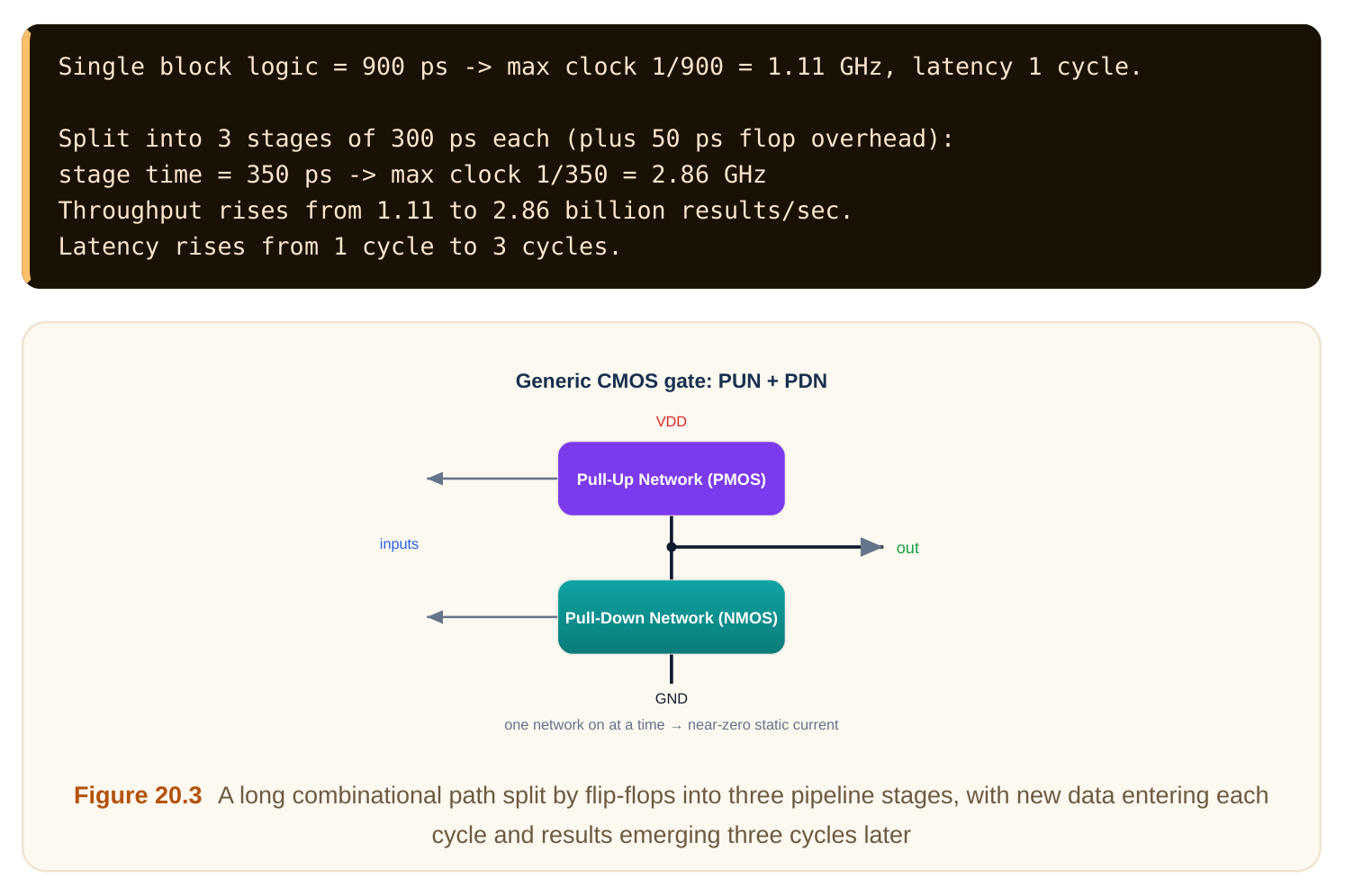
Pipelining means cutting a long logic path into shorter stages by inserting flip-flops. Each short stage can finish in less time, so the clock can run faster. Several pieces of work flow through the stages at once, like an assembly line. Two words to keep straight. Throughput is how many results come out per second. Latency is how long one result takes from input to output. Pipelining raises throughput but adds latency, because a result now passes through more flip-flop stages.
Clock gating is a power trick: when a block has no work to do, you stop its clock so its flip-flops stop toggling. Toggling burns dynamic power, so freezing the clock saves energy. A small gate (an ANDstyle enable) blocks the clock when an enable signal is low.
| Technique | Goal | Cost |
|---|---|---|
| Pipelining | Higher throughput | More latency, more flip-flops |
| Clock gating | Save dynamic power | Enable logic, slight skew risk |
| Time borrowing | Ease a tight stage | Needs latches, careful checks |
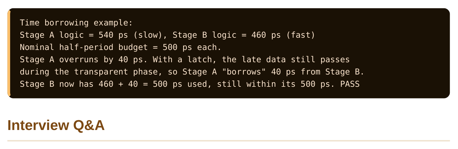
Time borrowing is a flexibility trick used with latches (memory cells that are transparent while the clock is high, unlike edge-triggered flip-flops). A slow stage can "borrow" a little time from the next stage, because a latch lets late-arriving data pass through during the transparent window. This smooths out stages that are not perfectly balanced.
time between two locations, caused by unequal wires and buffers. Jitter is the cycle-to-cycle wobble of the edge at a single location, caused by noise and supply changes. Skew is spatial; jitter is temporal.
length from the source, so the clock arrives at all of them at nearly the same time. This keeps skew very low by construction.
time to arrive. But the same skew hurts the hold check, so it must be controlled carefully.
stage so the clock can run faster. It raises latency because a single result now passes through more flip-flop stages before it appears at the output.
work to do. Idle flip-flops stop toggling, which cuts dynamic power. The cost is some enable logic and care to avoid glitches on the gated clock.
the transparent window, effectively borrowing time from the next stage. It helps when pipeline stages are not perfectly balanced.
Key Takeaways
- The clock distribution network must deliver edges to millions of flip-flops at nearly the same time.
- Skew is a fixed spatial difference in arrival; jitter is a cycle-to-cycle wobble at one point.
- An H-tree matches path lengths to keep skew low; meshes average out residual mismatch.
- Setup needs data early enough; hold needs data not too soon. Skew helps setup but hurts hold.
- Pipelining trades latency for throughput, clock gating saves power, and time borrowing rescues unbalanced stages.
Comments
Leave a Reply