 ChipBuddy
← Home
ChipBuddy
← Home
Static vs Dynamic Logic
Two Ways to Build Logic
Most chips are built from static CMOS logic. It is robust, simple, and forgiving. But there is another family: dynamic logic. It can be faster and smaller for some jobs, at the cost of being fussy and fragile. A good designer knows both, and knows when each fits. This chapter compares them in plain words. It covers static CMOS, dynamic and domino logic, and pass-transistor logic. The goal is to understand the trade-offs, not to memorise circuits.
Static CMOS, Restated
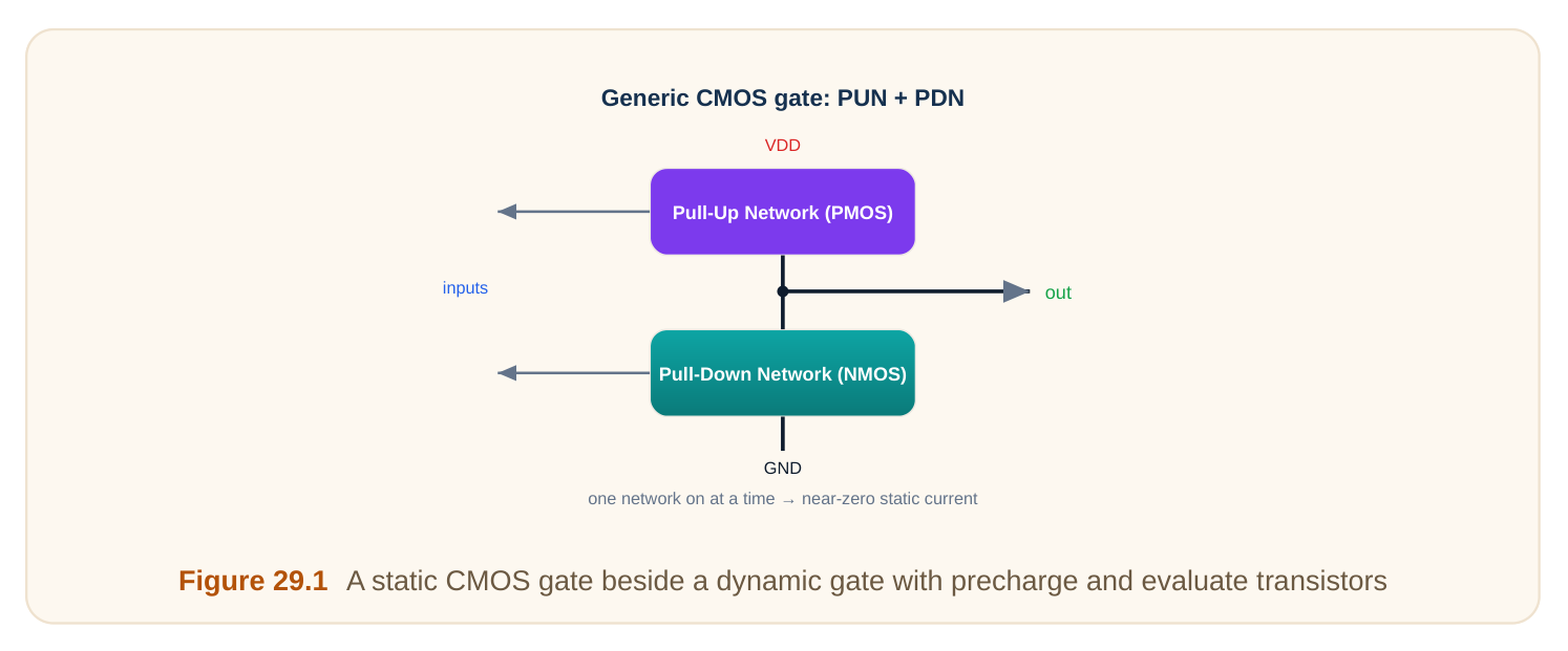
A static gate has two networks. A pull-up network of PMOS connects the output to the supply. A pulldown network of NMOS connects the output to ground. For any input, exactly one network is on. So the output is always firmly driven to a solid high or low. This is why static logic is robust. The output is never floating. It holds its value with no clock and resists noise. The cost is transistor count: every input needs both a PMOS and an NMOS, so a gate has two transistors per input.
| Property | Static CMOS |
|---|---|
| Output driven | always, firmly |
| Needs a clock? | no |
| Noise tolerance | high |
| Transistors | 2 per input |
| Speed | good, not extreme |
Worked example — transistor count
A 4-input static gate needs both networks.
PMOS: 4, NMOS: 4 → 8 transistorsEight transistors for one 4-input gate. The pull-up PMOS stack can also be slow, because PMOS is weaker. This is one reason designers looked for faster, smaller styles.
Dynamic Logic — Precharge and Evaluate
Dynamic logic drops the PMOS network. It keeps only the NMOS pull-down, plus two clocked transistors. It works in two phases driven by the clock.
- Precharge phase: a single PMOS, controlled by the clock, charges the output high. The pull-down is held off.
- Evaluate phase: the precharge PMOS turns off. A clocked NMOS at the bottom turns on. Now, if the inputs make a path through the pull-down, the output discharges to low. If not, it stays high. So the output is "pre-loaded" high, then either kept or pulled low. Only the NMOS network does logic. That means fewer transistors and a faster, lighter input load.
| Phase | Clock | What happens |
|---|---|---|
| Precharge | low | output charged high, pull-down off |
| Evaluate | high | output stays high or discharges low |
Worked example — transistor saving
The same 4-input logic in dynamic form:
NMOS logic: 4, precharge PMOS: 1, evaluate NMOS: 1 → 6 transistors
static was 8 → ~25% fewer, and lighter inputs
Fewer transistors, lighter input load, and only fast NMOS doing the work. That is the appeal.
The Catch: Dynamic Logic Is Fragile
The output of a dynamic gate, once precharged high, is only held by a tiny stored charge. Nothing actively drives it during evaluate if it is meant to stay high. That makes it easy to corrupt. Two main problems appear. Charge sharing: when internal nodes share charge with the output, the high level sags and may read as a false low. Leakage and noise: the held-high node slowly droops or gets bumped by a neighbour, again risking a wrong value. The fix is a keeper: a small, weak PMOS that gently tops up the high node during evaluate. It is weak enough that the real pull-down can still win, but strong enough to fight leakage and small noise. Even so, dynamic gates need careful design and clean clocks.
| Hazard | Cause | Fix |
|---|---|---|
| Charge sharing | internal nodes steal charge | add keeper, precharge internals |
| Leakage droop | held-high node leaks | keeper transistor |
| Noise on inputs | only NMOS, no PMOS guard | careful layout, keepers |
Domino Logic — Chaining Dynamic Gates
You cannot directly connect one dynamic gate to another. During precharge, every dynamic output goes high, which could wrongly trigger the next gate's pull-down. Domino logic solves this by putting a static inverter after each dynamic gate. The inverter makes the stage output start low during precharge. So the next stage's pull-down stays off until a real signal arrives. Stages then "fall" one after another like dominoes during evaluate. This lets dynamic gates chain safely, but every stage is now non-inverting (dynamic gate plus inverter), which limits the logic you can build.
| Feature | Plain dynamic | Domino |
|---|---|---|
| Can chain directly? | no | yes |
| Output during precharge | high | low (after inverter) |
| Logic polarity | any | non-inverting only |
Pass-Transistor Logic
A third style uses transistors as switches that pass a signal through, rather than as pull-up/pull-down networks. A control input opens or closes the switch, steering the data signal to the output. A multiplexer is the classic example.
This can be very compact: some functions need far fewer transistors than static CMOS. The downside is a weak or degraded signal. A single NMOS passes a strong low but a weak high; a PMOS the reverse. So pass-transistor designs often need a transmission gate (NMOS and PMOS together) and a restoring buffer to clean up the level.
| Style | Strength | Weakness |
|---|---|---|
| Pass-transistor | very compact | degraded levels, needs restore |
| Transmission gate | passes both levels well | two transistors per switch |
Worked example — mux transistor count
A 2-to-1 multiplexer in transmission-gate style:
2 transmission gates × 2 transistors = 4 transistors (+ a select inverter)That is compact compared with building the same mux from full static gates. The trade is the need to restore the signal afterward.
When to Use Each
Static CMOS is the default for almost everything: robust, easy, clock-free, tool-friendly. Dynamic and domino logic appear in a few speed-critical, regular blocks where the extra speed is worth the fragility and design effort. Pass-transistor and transmission-gate logic shine in muxes, selectors, and some arithmetic, where compactness pays.
| Need | Best style |
|---|---|
| General logic, robustness | static CMOS |
| Extreme speed, regular structure | dynamic / domino |
| Muxes, selectors, compact paths | pass-transistor / transmission gate |
Interview Q&A
and for any input exactly one is on, so the output is always firmly driven to a solid high or low. It never floats, holds its value without a clock, and resists noise — at the cost of two transistors per input.
output high while the pull-down is off. In evaluate, that PMOS turns off and a clocked NMOS turns on,
so the output either discharges low (if the inputs make a pull-down path) or stays high. Only the NMOS network does logic.
only by a tiny stored charge, so charge sharing, leakage, and noise can corrupt it. A keeper is a small weak PMOS that gently tops up the high node during evaluate — weak enough that a real pull-down still wins, but strong enough to fight leakage and small noise.
every dynamic output goes high, which could wrongly trigger the next gate's pull-down. Domino logic adds a static inverter after each dynamic gate so its output starts low during precharge, letting stages evaluate safely in sequence — but every stage becomes non-inverting.
which can be very compact (e.g. a mux). The downside is degraded signal levels — a single NMOS passes a weak high, a PMOS a weak low — so it often needs a transmission gate (both types) and a restoring buffer.
where the extra speed and smaller input load justify the fragility, clock dependence, and careful design that dynamic logic demands. For general logic, static CMOS is the robust, tool-friendly default.
Key Takeaways
- Static CMOS always drives its output firmly — robust and clock-free — but uses two transistors per input.
- Dynamic logic uses precharge then evaluate with only an NMOS network: fewer transistors, faster, but fragile.
- A keeper fights charge sharing and leakage on the held-high dynamic node.
- Domino logic adds a static inverter so dynamic gates can chain, at the cost of being non- inverting only.
- Pass-transistor / transmission-gate logic is compact (great for muxes) but gives degraded levels needing restoration.
Comments
Leave a Reply