 ChipBuddy
← Home
ChipBuddy
← Home
Sequential Circuits — Latches & Flip-Flops
Why a Chip Needs Memory
Plain logic gates have no memory. Their output only reflects their inputs right now. Change the inputs and the old result is gone. But real chips must remember things. They must hold a value while other logic computes. That is the job of sequential circuits (circuits that store state). A sequential element holds one bit. It keeps that bit steady until told to update. The clock (a steady on/ off timing signal) tells it when to update. This chapter covers the two main storage elements. They are the latch and the flip-flop.
The Storage Trick: a Feedback Loop
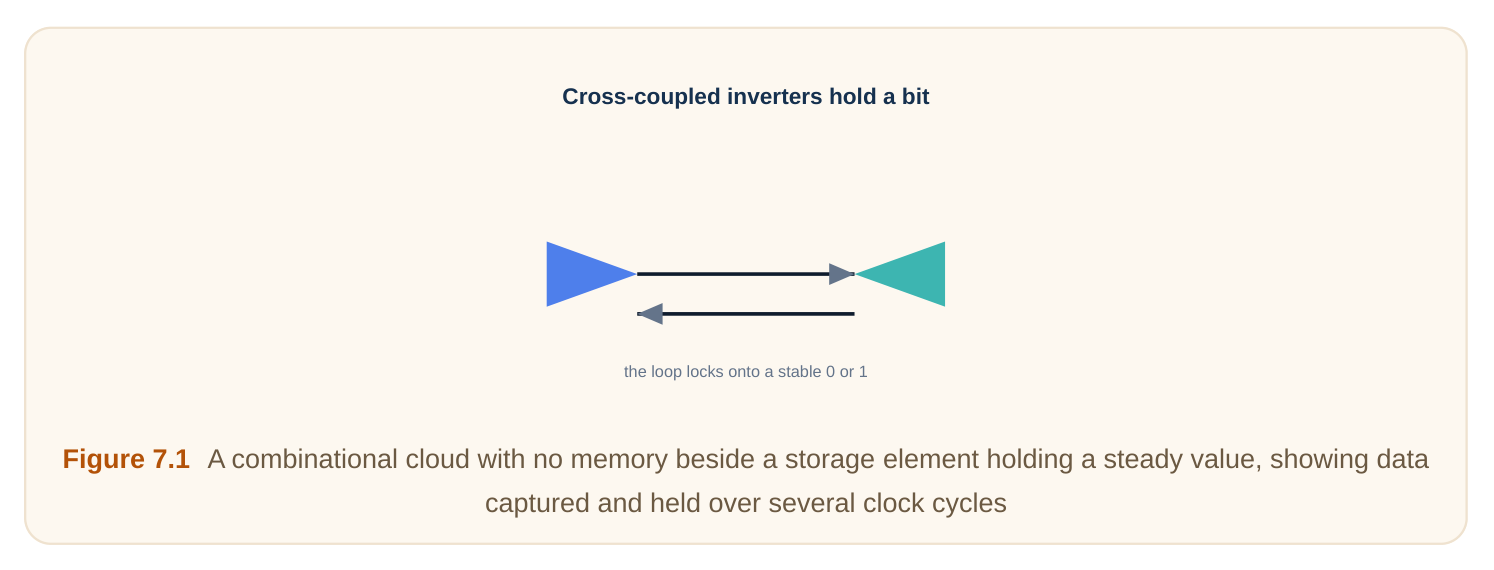
How does a circuit "hold" a bit? It feeds its output back to its input. Picture two inverters (NOT gates) in a ring. The output of one drives the other. The second drives the first. This loop is stable. It locks onto a 0 or a 1. It stays there with no outside push. This is called a cross-coupled pair (two inverters feeding each other). It is the heart of every latch and flip-flop. To write a new value, you briefly overpower the loop with a stronger input. Then you let the loop hold it again. Think of a light switch. It stays up or down on its own. You only touch it to change it.
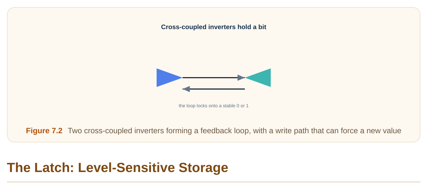
A latch is the simpler element. It watches the clock level (whether the clock is high or low).
- When the clock makes the latch "open", it is transparent (the output follows the input).
- When the clock makes it "closed", it holds (the output freezes at the last value). So a latch is like a gate on a path. Open means data flows through. Closed means data is trapped inside. A common build uses a transmission gate (a switch that passes a signal cleanly) plus the cross- coupled pair. When open, the switch lets new data in. When closed, the switch disconnects and the loop holds. The catch: a latch is transparent for a whole half-cycle. New data can ripple through during that time. This makes timing trickier. It also enables "time borrowing", covered later. Clock level Latch state Output behaviour Active (open) transparent follows input Inactive (closed) holding frozen at last value
The Flip-Flop: Edge-Triggered Storage
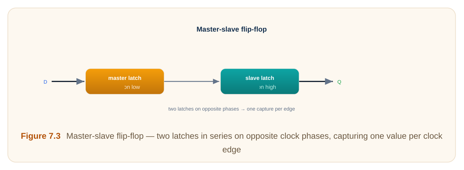
A flip-flop captures data only on a clock edge (the instant the clock switches, e.g., low-to-high). It does not stay transparent. It takes one snapshot per cycle. The usual build is the master-slave flip-flop. It chains two latches that open on opposite clock levels.
- The master latch opens while the clock is low. It tracks the input.
- When the clock rises, the master closes. The slave opens. It passes the captured value out. Only one latch is open at a time. So data cannot race straight through. The pair captures exactly one value, at the rising edge. This clean one-snapshot-per-cycle behaviour is why flip-flops dominate digital design.
| Feature | Latch | Flip-flop |
|---|---|---|
| Triggered by | clock level | clock edge |
| Transparent? | yes, half a cycle | no |
| Build | one latch | two latches (master-slave) |
| Timing | trickier (borrowing) | simpler |
| Area/power | smaller | larger |
The Three Timing Numbers
Every storage element has three timing limits. They exist because the internal switches and loop need real time to work.
- Setup time: data must be stable before the clock edge by this much. The master latch needs time to settle first.
- Hold time: data must stay stable after the clock edge by this much. The capture must finish before the input changes.
- Clock-to-Q: the delay from the clock edge to the new output. The value takes time to appear. If data arrives too late, you break setup. If it changes too soon after the edge, you break hold. Both cause a wrong or unstable capture. Parameter Plain meaning Broken when Setup time data steady before edge data arrives too late Hold time data steady after edge data changes too soon Clock-to-Q edge-to-output delay (a fixed cost, not a rule)
Worked example — maximum clock speed
A path goes from one flip-flop to the next. Use these numbers:
- Clock-to-Q = 0.10 ns
- Logic delay between flops = 0.55 ns
- Setup time = 0.08 ns The data must arrive one setup time before the next edge. So the smallest clock period is:
period_min = clock-to-Q + logic delay + setupperiod_min = 0.10 + 0.55 + 0.08 = 0.73 nsMax frequency = 1 / 0.73 ns ≈ 1.37 GHz. To go faster, cut the logic delay or use faster flops.
Worked example — a hold check
Hold can fail on a very short path. Use these numbers:
- Clock-to-Q = 0.10 ns
- Shortest logic delay = 0.04 ns
- Hold time = 0.06 ns
- Clock skew (capture clock later than launch) = 0.05 ns The new data reaches the next flop at 0.10 + 0.04 = 0.14 ns after the edge. The capture flop needs the old data stable until hold time plus skew = 0.06 + 0.05 = 0.11 ns. Since 0.14 ns > 0.11 ns, hold passes, but only by 0.03 ns. More skew would break it. The fix is to add a little delay on the short path.
Metastability: the Unavoidable Risk
What if data changes right at the clock edge? The flip-flop may not capture a clean 0 or 1. Instead its output can hover between them. This unstable state is called metastability (a balanced, undecided state).
Picture a ball balanced on a hill top. A tiny nudge sends it one way. But for a moment it just teeters. The output usually resolves to a real value. But the time it takes is random. It can, rarely, take too long. You can never make this probability exactly zero. You can only make it tiny. This matters most when two parts of the chip use unrelated clocks. To make a safe crossing, designers use a synchronizer. That is two or more flip-flops in a row. The extra flop gives a metastable value more time to settle. Each added flop lowers the failure rate sharply.
| Concept | Plain meaning |
|---|---|
| Metastability | output stuck between 0 and 1 |
| Resolution time | random time to settle |
| Synchronizer | 2+ flops to allow settling |
Reset, Enable, and Scan Variants
Real flip-flops add useful features.
- Reset/set: force the stored bit to a known value. Synchronous reset acts only at a clock edge. Asynchronous reset acts immediately, edge or not.
- Enable: the flop updates only when an enable signal is active. This holds the value across cycles without stopping the clock. It is the clean way to save power and skip updates.
- Scan flops: flops with an extra test input. In test mode they form a long shift chain. This lets a tester load and read every flop. It is the backbone of design-for-test. Variant What it adds Common use Reset/set force a known state power-up, control Enable update only when allowed hold value, save power Scan test shift path manufacturing test
Latch-Based vs Flip-Flop-Based Design
Most designs use flip-flops. They are simple to time and reason about. One snapshot per cycle keeps things clean. Latch-based designs are harder but can be faster. Because a latch is transparent for half a cycle, a slow stage can run a bit past the edge. It "borrows" time from the next stage's open window. This time borrowing can squeeze more speed out of tight paths. The cost is harder timing and more careful checking.
The simple rule: use flip-flops by default. Reach for latches only when you need that extra speed and can handle the complexity.
Interview Q&A
transparent while the clock is at one level and holds at the other. A flip-flop is edge-triggered. It captures one value at the clock edge and is never transparent. A flip-flop is usually two latches in a master-slave pair.
opposite clock levels. Only one is open at any time. So a new input cannot pass straight from input to output in one moment. The pair captures exactly one value per edge.
before the clock edge. Hold time is how long it must stay steady after. They exist because the internal latch and feedback loop need real time to sample and lock a value. Violating either gives a wrong or unstable capture.
between 0 and 1 after data changes too near the edge. It resolves in a random time, never with zero failure chance. Designers add a synchronizer (two or more flops in series) so a metastable value has extra time to settle before it is used. This is essential when crossing unrelated clocks.
on tight paths. A latch is transparent for half a cycle, so a slow stage can borrow time into the next latch's open window. The trade-off is harder timing analysis, so flip-flops remain the default.
Key Takeaways
- Sequential elements store state; they are built from a feedback loop (cross-coupled inverters) that holds a 0 or 1.
- A latch is level-sensitive (transparent then holding); a flip-flop is edge-triggered (one snapshot per edge), usually a master-slave pair.
- Three timing numbers govern them: setup, hold, and clock-to-Q; setup sets max speed, hold guards short paths.
- Metastability can never be fully removed; synchronizers (extra flops) make it rare, especially across unrelated clocks.
- Flops also come with reset, enable, and scan features; use flip-flops by default, latches only for extra speed via time borrowing.
Comments
Leave a Reply