 ChipBuddy
← Home
ChipBuddy
← Home
Electromigration & Wire Reliability
Electromigration and Wire Reliability
A chip can pass every functional test on day one and still fail two years later. The logic is fine. The transistors are fine. What wore out is a wire. Wires carry current, and current slowly damages metal. Over time a wire can thin, crack, or short. This chapter covers the physical effects that age wires and the design rules that protect them. The headline effect is electromigration. We also cover IR drop, self-heating, the antenna effect, and via reliability. Together these make up the field of wire reliability (keeping on-chip metal working for the product's whole life).
Electromigration: When Current Pushes Metal Atoms
Electromigration (EM, the gradual movement of metal atoms pushed by flowing current) is the slow erosion of a wire from the inside. Electrons flowing through the metal collide with metal atoms. Each collision gives the atom a tiny shove in the direction of electron flow. One shove does nothing. Trillions of shoves over years move enough atoms to matter. Where atoms leave, the wire thins. A thin spot has higher resistance and carries the same current in less metal, so it gets even hotter and thins faster. Eventually the wire opens, called a void (a gap where metal has been carried away). Where atoms pile up, the metal bulges and can push into a neighbor, called a hillock (a bump of accumulated metal that can short to another wire).
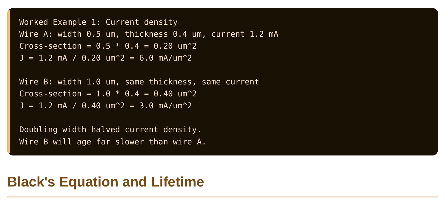
EM depends most strongly on current density (current divided by the wire's cross-sectional area, written J). A wide wire spreads the same current over more metal, so each spot of metal sees fewer collisions. A narrow wire concentrates the current and ages fast.
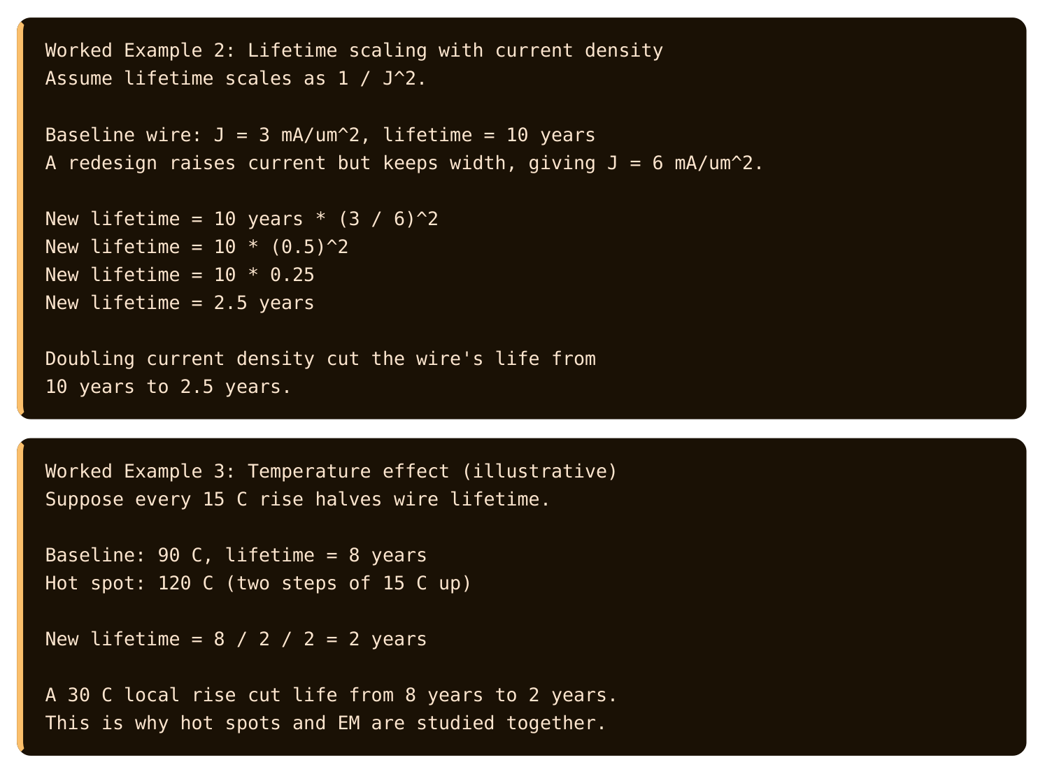
Engineers predict how long a wire lasts before EM kills it. The standard model is Black's equation (a formula for the median time before an EM failure). Its shape, in plain words, is: Lifetime is inversely proportional to current density raised to a power, and it gets much shorter as temperature rises. Two terms drive everything. Current density appears raised to a power, usually around two, so doubling current density cuts life by roughly four times. Temperature appears in an exponential term, so a small temperature rise shortens life sharply. Hot, crowded wires die young.
The current that matters for EM is not always the same. A wire that carries current steadily one way is the worst case, because atoms march in one direction with no relief. A wire that carries current back and forth gets partial healing, because reversed current pushes some atoms back. So designers use different current limits for one-way and back-and-forth wires.
| Current type | EM stress | Limit used |
|---|---|---|
| Steady one-way (power) | Worst, no healing | Lowest current allowed |
| Back-and-forth (signal) | Some self-healing | Higher current allowed |
| Short pulses | Brief, mild | Highest current allowed |
IR Drop: Voltage Lost in the Power Wires
Every wire has resistance. When current flows through resistance, it drops voltage. On the power network this is called IR drop (the supply voltage lost across the resistance of the power wires, from I times R). The gates at the end of a long, thin, busy power wire receive less than the full supply voltage. A gate starved of voltage runs slower and may even malfunction. So IR drop is both a timing problem and a reliability problem.
Worked Example 4: IR drop on a power rail
Power rail resistance from source to a block = 0.8 ohm
Current drawn by the block = 250 mA
IR drop = I * R = 0.250 A * 0.8 ohm = 0.20 V
If the supply is 1.0 V, the block actually sees:
1.0 V - 0.20 V = 0.80 V
A 20% voltage loss. The block runs slow and may fail timing.
IR drop ties into EM directly. A wire wide enough to keep IR drop small is also wide enough to keep current density low. So designers size power wires to satisfy both at once. The power network is built as a dense mesh (a grid of many parallel power wires) so current has many paths and no single wire is overloaded.
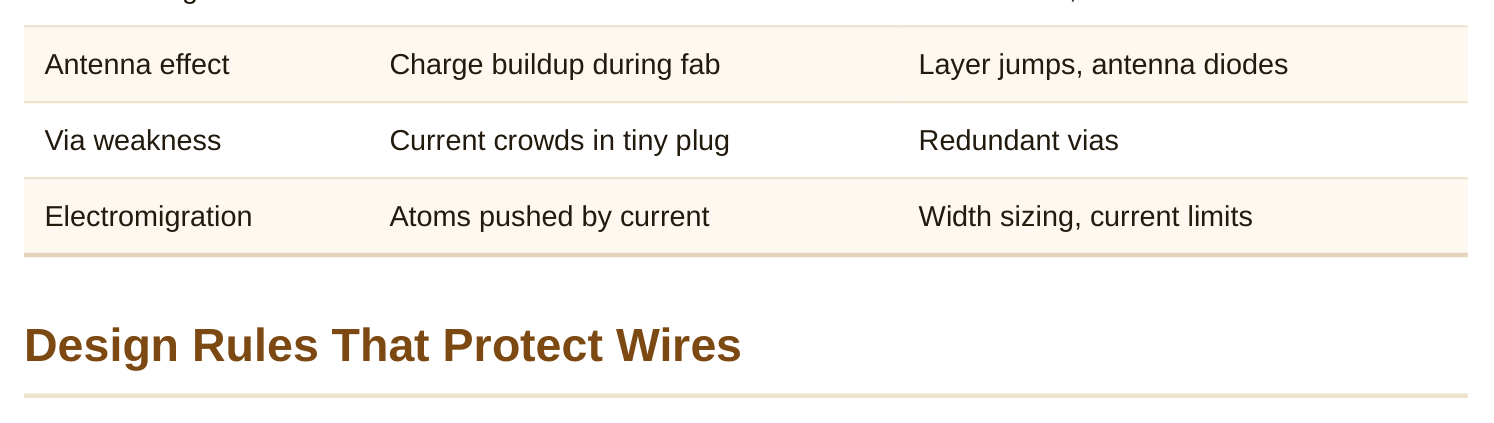
Three more effects round out wire reliability. Self-heating is a wire warming itself with its own current. The same I times R that causes IR drop also turns into heat right inside the wire. A wire surrounded by insulators cannot shed heat well, so it runs hotter than the silicon around it. That extra heat speeds up EM, since EM worsens with temperature. Self-heating and EM feed each other. The antenna effect is a manufacturing hazard, not a runtime one. During chip fabrication, a long metal wire that is connected to a transistor gate but not yet to anything else can collect charge from the plasma used in processing. That collected charge dumps into the thin gate oxide and can punch through it, damaging the gate before the chip ever runs. The fix is to give the charge somewhere safe to go. Designers break long wires with jumps to a higher layer, or they add a small diode (a one-way device that bleeds charge to the substrate). The antenna ratio (collected metal area divided by gate area) must stay under a rule limit.
Worked Example 5: Antenna ratio check
Metal area connected to a gate = 4.0 um^2
Gate area = 0.05 um^2
Antenna ratio = 4.0 / 0.05 = 80
If the rule limit is 50, this fails.
Fix: route part of the wire up a layer to cut the
connected metal, or add a protection diode at the gate.
Vias are the small vertical plugs that connect one metal layer to the layer above. They are tiny, so current crowds through them. A single via can become a current-density hot spot and an EM weak point. The standard defense is redundant vias (using two or more vias where one would do). If one via voids, the others keep the connection alive, and the shared current lowers density in each.
| Effect | Cause | Defense |
|---|---|---|
| Self-heating | Wire heats itself with I*R | Wider wires, current limits |
Foundries hand designers a rulebook. Several rules exist purely to keep wires alive for the product's lifetime. Current-density limits cap how much current a wire of a given width may carry. To carry more current, you widen the wire or use more parallel wires. Tools check every wire's current against its width automatically. Minimum width and spacing rules keep wires from being too thin to survive or too close to short via a hillock. Power wires often have larger minimums than signal wires because they carry steady one-way current. Via rules require enough vias for the current passing through, often demanding redundant vias on high-current and reliability-critical nets. Antenna rules cap the antenna ratio at every gate during routing.
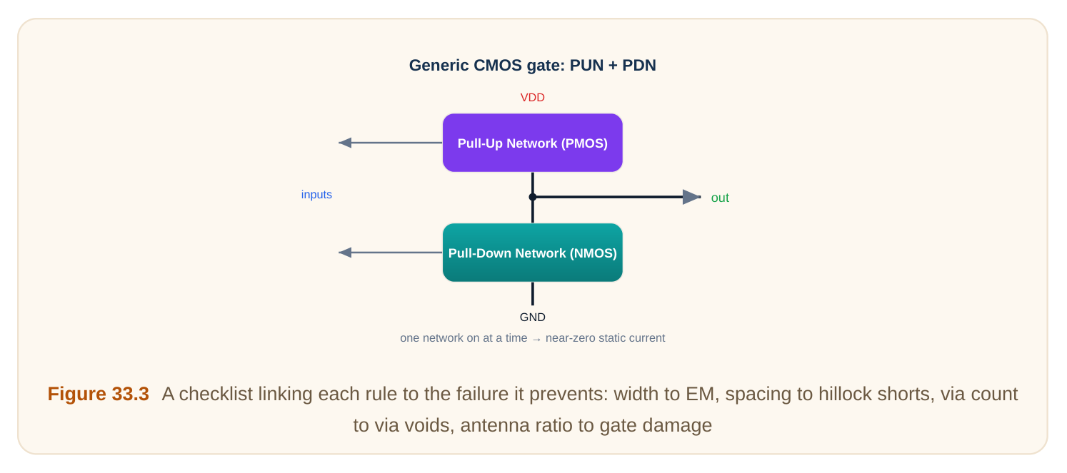
| Design rule | Failure it prevents |
|---|---|
| Current-density limit | Electromigration void |
| Minimum width | Thin-wire EM and breakage |
| Minimum spacing | Hillock short to neighbor |
| Via redundancy | Open from a voided via |
| Antenna ratio limit | Gate oxide damage in fab |
These rules are not optional polish. A design that violates them may pass every test at tape-out and then fail in the field months later. That is the worst kind of failure, because it reaches the customer. So reliability checking sits firmly inside the sign-off flow, right next to timing and power.
Interview Q&A
and nudge them along. Over years, enough atoms move that the wire thins in one place, forming a void that raises resistance and eventually opens the wire. Where atoms pile up, a hillock can bulge out and short to a neighbor.
crowded the current is, not just how much there is. A wide wire spreads the same current over more metal, so each region sees fewer collisions. Current density, current divided by cross-section, captures this crowding, which is why widening a wire helps.
with current density raised to a power, roughly squared, so doubling density cuts life about fourfold. Lifetime also drops exponentially with temperature, so hot wires fail much sooner. It guides current limits.
current. IR drop is the voltage lost across that resistance; EM is the atom damage from the current density in it. Sizing a power wire wide enough to limit IR drop also lowers its current density, helping EM at the same time.
gate can collect plasma charge and punch through the thin gate oxide before the chip ever runs. Designers break the wire with a jump to a higher layer or add a small diode to bleed the charge safely to the substrate.
weak point and a single point of failure. Adding extra vias shares the current so density drops in each, and if one via voids, the others keep the connection alive.
Key Takeaways
- Electromigration moves metal atoms under current, forming voids that open wires and hillocks that short neighbors over the product's life.
- Current density is the key EM driver, so widening wires or adding parallel wires lowers stress and extends lifetime.
- Black's equation links lifetime to current density and temperature, with hot, crowded wires failing fastest.
- IR drop steals supply voltage in the power network, hurting both timing and reliability, and is fought with wide wires and a power mesh.
- Design rules for width, spacing, via redundancy, and antenna ratio exist to prevent field failures and are checked at sign-off.
Comments
Leave a Reply